Hi all!
This is my first Topic here, so if am I doing something wrong, please, be patient and tell me ( :
I am doing a project for a Logitech G27 racing wheel where the potentiometer is replaced by a load cell on the brake pedal to increase the feeling of breaking. For this I would like to use an Operational Amplifier to increase the signal level and use the original connectors where was the potentiometer. Searching on internet forums I founded the INA122PA OpAmp, which is very used in this case of breaking pedal, so I make a circuit on protoboard using it, but the problem is, the signal level does not change when applied force to the sensor. I had already tested two kinds of sensors, revised the circuit end tried a lot of things, but I don't find any solution on internet or by myself.
Below you can see the diagram of the circuit that was done:
Below you can see the tension on the output, it is important to say that there is no current on Rg (potentiometer to adjust the output), and changing it does not affect anything:
Components:
OpAmp: INA122PA.
Power Supply: 5V from Arduino Uno or Mega.
Potentiometer: Trimpot 1k ohm.
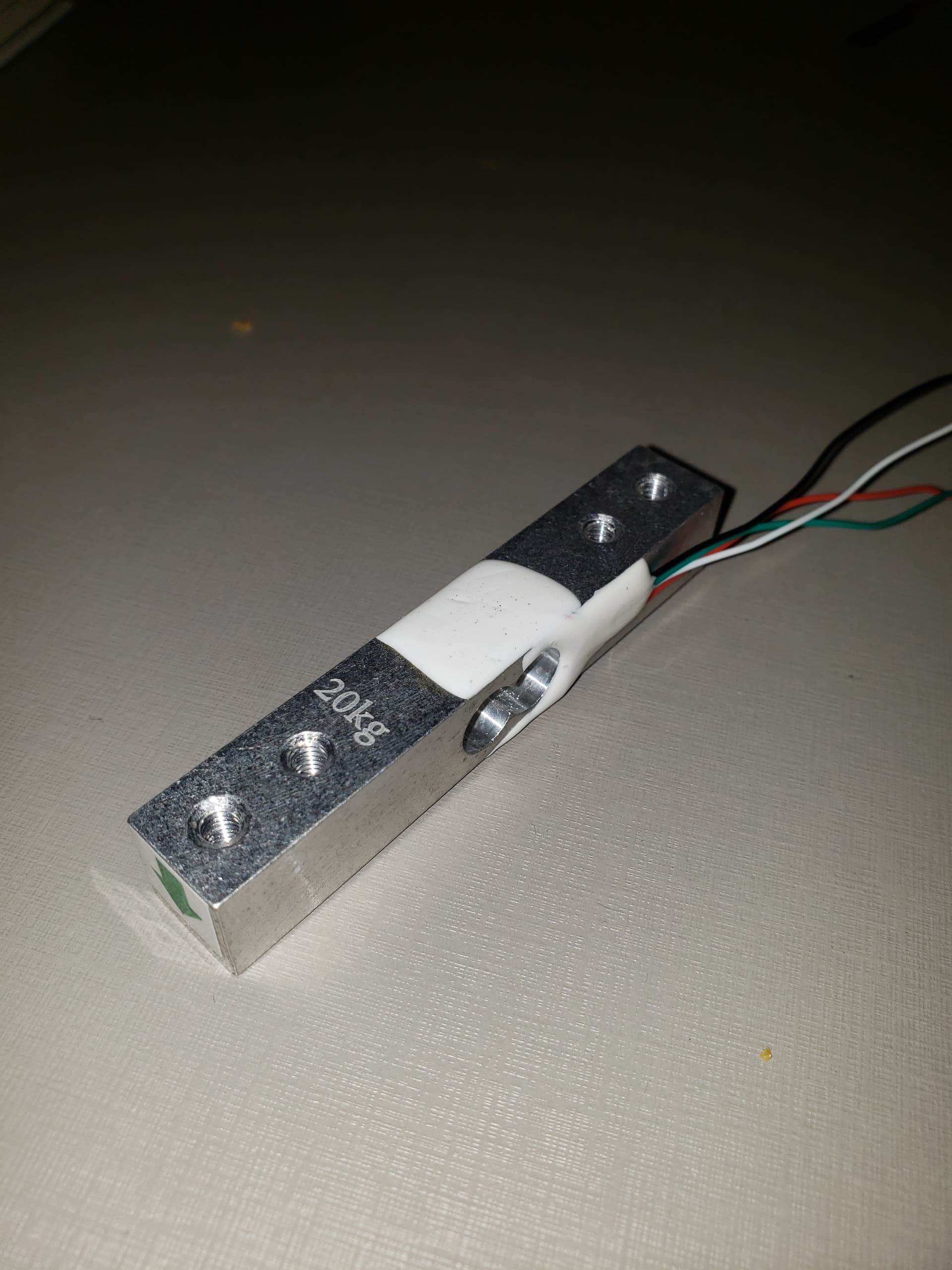
Load cell: Bath Scale load cell or 20 kg load cell like the below (I have tried with both).
A schematic would be much easier to follow. I do not have the time to look up the parts and associated pinouts then guess at what the resistance is or the picture it connects to.
Produce the schematic as you have it wired then compare them. You have a pot set to ??? You have a load cell??? You might consider using a HX711 breakout board. Try this link: SparkFun Load Cell Amplifier - HX711 - SEN-13879 - SparkFun Electronics also click on the documentation and look at there schematic. Let us know how you do.
All the images that I posted was taken by me with the components that I used. I am using a pot set of 1k Ohm, and a 20 Kg load cell.
I would like to use the HX711 because I had already tested It and I managed to measure the signal, but I need a analog output instead of digital output provided by HX711.
So you're not going to use an Arduino or other processor then, because the first thing an Arduino does is change it to digital. And the Arduino does that with a much lower resolution than an HX711.
With the pot set to 1k ohm, gain of the INA is about 200,
so if there is something wrong at it's inputs, it's 200x wrong at it's output.
A lower pot value increases the gain, so could make a fault worse.
First measure bias voltage on pin 2 and 3 of the chip with respect to ground.
It should be half of the chip's supply voltage (2.5volt if VCC is 5.0volt).
Then measure the voltage difference between pin 2 and 3 (DMM connected to 2 and 3).
It should be close to zero millivolt. That value is going to be amplified 200x.
25mV difference on it's inputs will peg the output towards VCC,
or it will disappear below ground (if it could).
If you can get the inputs close to zero mV (might have to bend the load cell carefully),
then make sure a load on the load cell is going to produce a more positive voltage,
or else swap the input connections.
You should have a decoupling cap between VCC and GND of the chip, close to the chip.
Leo..
Your schematic shows a current source, I do not see it anywhere in anything you have shown. The HX711 gives you the value of the analog signal as a 24 bit binary number. You can send that to a DAC and get an analog voltage. You have not given us a clue as to what you are going to do with the output voltage, so far all we know is you are using a meter that will not come close to measuring several of the values involved. You could possibly use a dash-pot or spring for a lot less money then the load cell. You stated you tried two cells and they did not change, how did you determine that?
Hi, @AdrianoMunin
Can you describe, what you mean by continuous reading?
There will always be a time between readings are taken, for the controller to process and output what the input has presented.
If you input analog then an AtoD process has to take place before processing, this takes time.
How fast do you want to sample your brake pedal output?
@Wawa responding to your topic:
For the first part of the project, I will not use an Arduino, because I am replacing a Potentiometer, so I need the analog signal.
With the pot set in 1K, I made the tests, and with everything connected I measured the PIN 2 and 3 of INA122. The voltage was the half of input (2.2V with VCC being 4.4V ) on both pins.
With the load cell connected just to the power supply, the difference between pin 2 and 3 of the load cell is 0mV and if I apply force on the load cell with my hand, I get 1,4mV.
In all scenarios, the output does not change. If I remove the load cell the output is in 3.81V, and if I connect the load cell the output is the same (3.81V).
No, I am not using a decoupling cap between VCC and GND, I am using everything directly on the power supply (5V Arduino Uno) and protoboard.
@gilshultz responding to your topic:
My current source is a 5V from Arduino Uno, on the diagram below, represents the circuit that I made, the power source is represented by the red wire.
What is happening with the output voltage is that It does not change, when I apply a weight to the load cell. The loadcell changes its output, but nothing happens on the INA122, even I remove the Rg, nothing happens.
I tested two different kinds of cells separately to eliminate the possibility of the problem being on the cell.
@TomGeorge responding to your topic:
When I tell continuos reading is that the output of the INA122 does not change no matter what I do. If apply weight on the loadcell or remove the pot (Rg), nothing happens, the output keeps on the same voltage.
Then gain is 5x, and with the measured values you posted the output should be close to 0volt.
Your breadboard/wiring looks ok, so I expect the chip to be faulty.
Leo..
The 5V from the Arduino is a voltage source, not a current source. Try adding a resistor in the 25K range in series with the 5V to the sensor. That will act like a pseudo current source.
I have tried to associate 2 resistors of 10K Ohm in series to generate resistance of 20k on the 5V of the Load Cell, but I am still having the same problem. I have tried with 30K ohm too.
To test the chip...
Remove the load cell and remove the trimpot.
Use a 1k:1k voltage divider between VCC and GND of the chip,
and connect both pin 2 and 3 to it's center tap.
The unconnected output pin (pin6) should now measure close to zero volt.
As said, don't forget a decoupling cap across the supply of the chip, say 47uF.
Weird things can happen if you omit decoupling.
Leo..
On this test Vcc was 5V, but the output stays on 4.53V instead of 0V which was expected. I tested two different units of INA122, but they have the same behavior.
I also tested some capacitors configurations for the decoupling cap, I have tested circuits with 100uF, 50uF, 10uF, 20uF, 30uF, 200uF, 100pF, 10pF, but all with the same behavior.
And measure directly on the pins of the chip.
Yes, pin 2 and 3 should be mid-voltage, and joined for testing.
And try another area of that breadboard. Some (most) are crap.
Leo..
Measure your resistors.
Midpoint of a two-resistor voltage divider with equal resistors should be half of the supply voltage.
2.5volt, not 4.7volt.
Leo..
Hi,
I changed the project, now I am using the HX711 to read the load cell signals and an AtTiny85 as DAC converter, so in this case, I can implement more functions on my project.