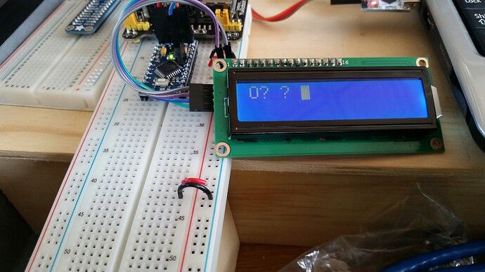
Contrast problem using 1602A LCD over I2C [SOLVED]

I am using a Pro mini clone, 1602A v2.0 white on blue LCD, and a unmarked I2C backpack with PCF857 chip; all purchased cheaply via auction site.

The screen displays BUT, it appears to be blue text instead of white, like the text is inverted and nearly impossible to read. Adjusting the potentiometer on the backpack will dim the display to nothing, but that is all. In the first pic you can see a faint 'Hello, world!'. That is the best readability I could get. (The unconnected LCD and backpack in the pics are identical to the ones in use (that I soldered together before testing).)

The second pic shows an interesting accident - I disrupted the wiring to the backpack while troubleshooting using a more complex sketch and the screen displayed two updating characters - but at full brightness and contrast! Proof of operation? Any clues?

The simple sketch on the first pics is:

//YWROBOT
//Compatible with the Arduino IDE 1.0
//Library version:1.1
#include <Wire.h> 
#include <LiquidCrystal_I2C.h>

LiquidCrystal_I2C lcd(0x27,16,2);  // set the LCD address to 0x27 for a 16 chars and 2 line display

void setup()
{
  lcd.init();                      // initialize the lcd 
 
  // Print a message to the LCD.
  lcd.backlight();
  lcd.print("Hello, world!");
}

void loop()
{
}

This is only my second arduino project and electronics is a new hobby for me.

CEG003400.rar (1.08 MB)

Y679???.pdf (852 KB)

It's not a contrast problem it is a backlight problem. The backlight is OFF in your first picture and it is ON in your second picture.

You might want to read through this thread Arduino i2c for 16x2 lcd no backlight or text after upload [solved] - Displays - Arduino Forum since it deals with a similar I2C adapter.

Don

Thanks for the reply Don. It may be hard to see in the picture, but the LED indeed seems to be on, it is just the text that is not illuminating correctly. Pulling the jumper off the backpack I can clearly see the LED turn out.

I looked at the thread you suggested and here's what I tried:

Using an i2c scanner I was able to determine that the address of the board is 0x27 (like in the manufacturer supplied sketch).

I removed my LiquidCrystal folder and replaced it with the one from the thread you linked by FM.

I ran the HelloWorld_i2c sketch; It uploaded successfully but produced no response.

By changing the line:
LiquidCrystal_I2C lcd (0x38)
To:
LiquidCrystal_I2C lcd (0x27)
Gave me a flicker of the LED on reset. This is the address used in the manufacturers sketch.

By changing to:
LiquidCrystal_I2C lcd (0x27, 3, POSITIVE)
The backlight stayed on, but no text.

And changing to:
LiquidCrystal_I2C lcd(0x27, 2, 1, 0, 4, 5, 6, 7, 3, POSITIVE);
Same. Backlight and no text.

By simply deleting lots of stuff in FM's HelloWorld_i2C sketch I was able to get some random characters on the screen, backlit properly!

So my troubleshooting may indicate that the manufacturers files (from post 1) work - but without proper lighting, and the things I have tried give me a backlight, but no text. I feel certain that all the pieces are here, I just don't have the experience to figure it out.

I tried to run the i2cLCDguesser but it hung at the press send to continue prompt.

I tried to run the i2cLCDguesser but it hung at the press send to continue prompt.

Did you make sure to follow instruction #6 in the guesser to set the line ending for Newline. It's selected in the little box next to the baud rate in the serial monitor of the IDE.

  1. Press the key or [Send] button to advance to next guess
  • NOTE: Make sure to select a newline as the line ending and
  • if using the key you must first click on the text box
  • to give it focus.

Hi cattledog,
I did not follow the i2cLCDguesser instructions properly - it ran successfully after I set the line ending to Newline as you suggested - thanks.

It detected the device : PCF8574 at address 0x27

Unfortunately the guesses did not print any text on the screen. The first guesss flashed the backlight and ended with backlight on. The second guess flashed the backlight and ended with backlight off. The remaining guesses did nothing.

If I could somehow integrate the partially working manufacturers code with the backlight progress I have so far...

EDIT- The constructor was printed to the screen, but I could just barely see it. Check out the pic. Any ideas?

It may be hard to see in the picture, but the LED indeed seems to be on, it is just the text that is not illuminating correctly.

OK I see that now. Maybe it is indeed a contrast problem!

I see that the power connections for the I2C adapter are taken from opposite sides of your power supply it the two pictures. Both sides appear to be configured for 5 volts, but have you actually checked?

You also mentioned disrupting the wiring between the two pictures. Have you carefully inspected all of your connections looking especially for 'cold' solder joints?

Have you tried the other LCD module?

Don

Hi Don,
Both power rails in my setup are at 5v. When I 'disrupted' the connections earlier I was pulling and inserting cables and the screen glitched into the second picture in POST 1. I would be nervous about trying to recreate it. It hasn't helped me solve anything but I was so excited to see a proper character resolved on the screen. I am glad I took a picture; it hints that the screen is capeable of displaying correctly without hardware changes.

I bought two screens and two backpacks - both sets behave the same so it probably isn't the solder joins.

It looks like the screen pixels are the opposite of what they should be; they should be white, not blue. The characters on the screen are actually darker than the background. Does that make any sense?

I don't know if you have any data sheet on the lcd you bought, but it looks like a positive, transflective model. Often, these require negative contrast voltage.

I don't quite remember the procedure, but Don recommended one using a battery to check this out. Start by grounding the contrast pin and see if it improves.

I recommend trying the display without the I2C adapter to determine if it works as expected.

Don

You should be able to hook up only the power connections to the i2c backpack and then
adjust the contrast pot to see some pixels.

You should be able to see a row of blocks on the display which is the default powerup
state of the LCD.

--- bill

Yes, fair go from the guys telling him to muck about with the sketch - he already had it displaying "Hello World!"

Obviously the software was working; just keep it in whatever version it was working.

The fortuitous second photo gives the clue. There is a bad connection in there somewhere - check pins 1, 2 and 3 on the backpack/ LCD assembly for starters. Second to that, check the voltages on those pins (pin 3 should be set around 0.5V).

Thanks for the replies, all.

You guys are gonna love this one:

Trying the display without the I2C adapter gave same inverted contrast.

Connecting only the power and ground on the backpack gave me a lit screen with no pixels visible at all (adjusting contrast did nothing).

At Paul's suggestion to check the voltage on pin 3, I took a multimeter to the power supply rails and I only had 3 to 4V! I looked up from my bench to see that I was feeding my breadboard power supply from a 5V wall wart...

Don asked me if I checked this - and I just confirmed my jumper position and moved on. --> He had this solved this two days ago if I had only listened explicitly.

Supplying the incorrect voltage to my breadboard was causing the crazy dim and inverted contrast. My 5V pro mini was working just fine on this low voltage. Moral of the story: Breadboard power supplies like the one I was using must be supplied with more than 5V in order to feed 5V to the breadboard. I found a 12V wall wart I had lying around and the screen lit up bright as day, perfect contrast!

I then hooked up the original lcd via I2C backpack and it worked right off (pic) with the manufacturer supplied sketch.

Thanks everyone for the help.

2 Likes

Supplying the incorrect voltage to my breadboard was causing the crazy dim and inverted contrast. My 5V pro mini was working just fine on this low voltage.

Let me explain a little more about what happened here. Not only was your pro mini working on the lower voltage, the LCD module was working as well --- except for the contrast.

The contrast voltage is specified with respect to VCC not GND. Typically this voltage is around 4.5V less than VCC which would be 0.5V with respect to GND when operating with a 5V supply. When you operate this same display at 3.5 V the required contrast voltage would then be around -1.0V but the best you can get with your potentiometer is 0v.

Moral of the story: Breadboard power supplies like the one I was using must be supplied with more than 5V in order to feed 5V to the breadboard.

This is true of virtually all voltage regulator circuits. There is a minimum input-output differential required for them to function properly. This differential is typically at least 2 volts but there are 'low-dropout' versions that require less.

Don

boxfresh:
Moral of the story: Breadboard power supplies like the one I was using must be supplied with more than 5V in order to feed 5V to the breadboard.

I find it much easier to use USB to power the breadboard adapter.
A computer is already needed to build the code, might as well use one of the USB ports
to power the breadboard.

--- bill

1 Like

boxfresh:
You guys are gonna love this one:

It was very obvious (at least from my point of view) that you were not getting sufficient voltage. The question was then why.

Using the wrong power supply is certainly one way for that to happen. The problem is that few of us here would imagine not knowing how a regulator (which we of course know to be on that power module) works.

Obviously. XD

And by the way - there are 3.3V versions of the display. They are the same board, but with a "charge pump" fitted to the "U3" location on the board and some extra capacitors, which powers the contrast voltage, not the chips or LED.

The other interesting consideration is what you accidentally did to temporarily supply the full 5V to the display.

Well I certainly came to the right place for help. May my oversight be easy for other novices to find, just before they post such a confusion as mine. For your efforts gentlemen, I am grateful.

Don't use the USB cable as a power supply for your LCD..... I learnt the hard way! Use an external power supply, regulated down to 5v to power the LCD, (and the Arduino if need be) ...... Everything works fine, now...

If you need an external power supply for a 16x2 LCD, there is something wrong.

The backlight should only take 50mA or so. The actual HD44780 takes less than 1mA.

Most 16x2 modules have a series resistor to set a sensible backlight currrent.
Some modules have a 0R resistor mounted n the pcb. They expect you to provide the series resistor.

The backlight LED will be damaged by a high current. You can measure the actual current with a DMM.

David.