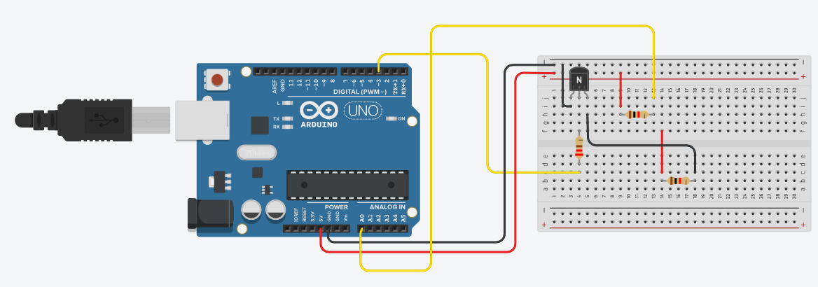
What am I doing wrong if current flows through the PN2222A transistor even when digitalWrite is set to LOW? There is a 1000 Ohm resistor connected before the Base. There is no external power source, only the Arduino 5V.
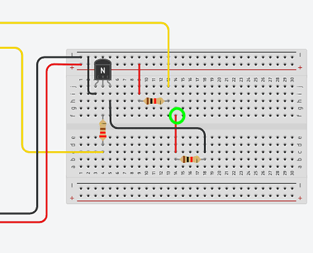
In the picture, the bottom resistor would be the unknown one that I will measure. The right side is the known 2000 Ohm resistor.
Code:
const int basePin = 3;
const int analogPin = A0;
const float knownResistor = 2000.0;
int current = 1;
void setup() {
Serial.begin(9600);
pinMode(basePin, OUTPUT);
}
void loop() {
if (current == 1) {
digitalWrite(basePin, HIGH);
delay(100);
int analogValue = analogRead(analogPin);
float voltage = analogValue * (5.0 / 1023.0);

float currentFlow = voltage / knownResistor;
float unknownResistor = (5.0 - voltage) / currentFlow;

Serial.print("Unknown resistor: ");
Serial.print(unknownResistor);
Serial.println(" ohm");

digitalWrite(basePin, LOW);
} else {
digitalWrite(basePin, HIGH);
delay(100);
int analogValue = analogRead(analogPin);
float voltage = analogValue * (5.0 / 1023.0);

float currentFlow = voltage / knownResistor;
float unknownResistor = (5.0 - voltage) / currentFlow;

Serial.print("Unknown resistor: ");
Serial.print(unknownResistor);
Serial.println(" ohm");

digitalWrite(basePin, LOW);

delay(1000);
}
}
According to the simulation in Tinkercad, it should work. When current = 1, digitalWrite is HIGH; when current = 0, digitalWrite is LOW. However, when assembled, the serial monitor shows 5V and 2046000 Ohms when LOW.