I need some help for a project. I want to use an IR Remote to Control my RF controlled TV Lift.
I control my TV with a Harmony Elite IR control and want to build a marco in the Logitech Harmony software that puts the lift in viewing position after switching-on the TV and reverts the Lift back to storage position upon switching-off the TV.
The only problem: my Harmony cannot use RF and thus cannot communicate with the TV Lift. Initially I thought to build an Arduino IR to RF converter, but maybe I can also do it easier.
My plan is to build a "remote for the remote":
My Harmony IR remote control will send 2 IR signals to my Arduino that is soldered to the two relevant buttons from the TV lift RF Remote control. Instead of physically pressing the button, the Arduino controls the buttons. Everthing will be attached to the USB Port of the TV, so when it's switched on, the Arduino & connected RF remote will power up.
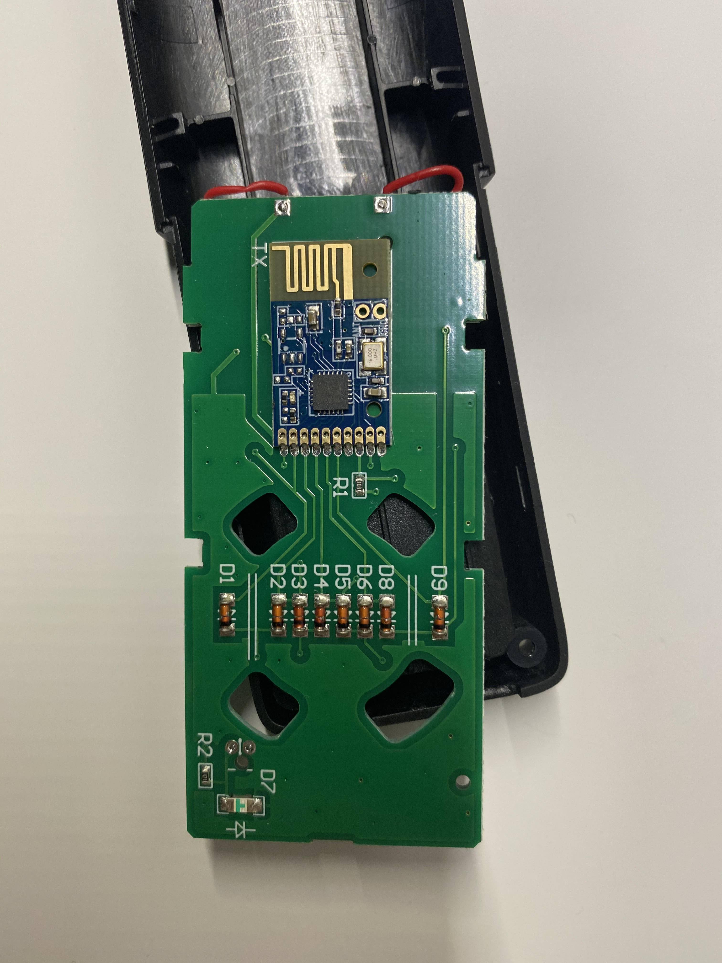
I have a RF Remote control (RMT-02-PJ) with several buttons that controls the TV Lift (HP 33-1L). After initial setup of the TV lift, I now only need two buttons that do the following:
Button1 ("K1") - if pressed once, duration does not matter- lifts the TV in the viewing position.
Button2 ("K8") puts the TV Lift back to storage position.
I started building a program and wired a circuit on a breadboard that lets me control 2 LEDs with my IR remote - upon pressing a button on the IR remote, the LED goes on, upon pressing it again it goes off. Two different buttons, two different LEDs. IR receiver is connected to Pin8, LED1 to Pin7, LED2 to Pin8. The idea is now to replace the LEDs with the buttons K1 and K8 on the RF control.
My current problem:
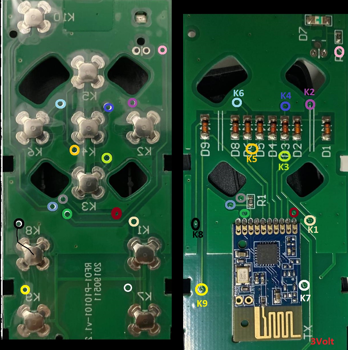
How to now connect the Arduino to the RF Remote buttons of the TV lift (where to solder, how to do the wiring, any resistors needed)? The two buttons that need to be controlled are K1 and K8 on the picture below.
Also, do I have to change the sourcecode (https://pastebin.com/wzaV1HvP)? The LEDs currently are controlled ON/OFF - for the TV Lift I only need to press a button once.
Replace or add opto couplers to the current LED outputs, the o.c. outputs to the remote buttons. Check the polarity of the button pins, connect emitter to the negative and collector to the positive pin.
For single shot signals see the BlinkWithoutDelay example and replace the toggle operation by all outputs always off. Then on receipt of the command turn the related output on and start the blink period.
For a crude ratsnest proof of concept, you could use small relays to interface. Then move to optocouplers as a refinement once you know it will all work.
Thanks for your replies, I maybe should have added that I am not very versatile with electronics and just have an Elegoo Arduino Super Starter kit (list of components included can be found here).
My naiive idea was just to solder a cable that connects the pin of the arduino that was intended to send a signal to the LED to the RF remote instead.
So I thought I would connect the cable that feeds the Anode of my first LED with the Diode on the RF:
Arduino Pin 7 to RF circuit D9, getting signal from K8 (black)
Arduino Pin 8 to RF circuit D1, getting signal from K1 (sand)
Thanks for the code suggestion (BlinkWithoutDelay) - that's pretty straight forward.
Remaining questions:
What does the Optomenter do and why do I need it for my example? EDIT: "he main function of an opto-isolator is to block such high voltages and voltage transients, so that a surge in one part of the system will not disrupt or destroy the other parts" - So you want me to use it to protect my circuit from damage and random signals recieved?
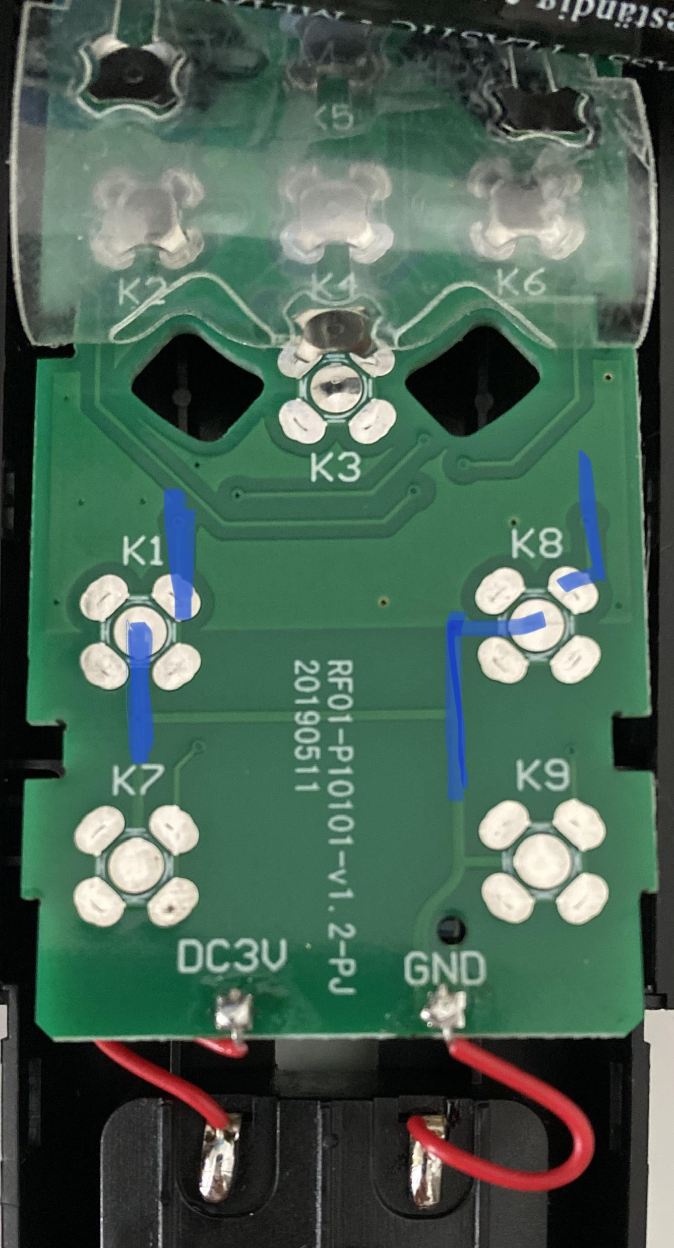
The RF circuit is powered by two AA batteries, but the input reads 3V. Can I also just add a 3V pin from my arduino to power the RF circuit? Or do I have to stay with the AA batteries?
Electric circuits deserve 2 wires, a common wire is usually named GND (ground).
As long as the RF button interface is unknown, incompatible signal levels can cause damage even at low voltages. That's why isolation by relays or opto couplers is required.
If you use a 3.3V Arduino both devices can be powered from the same batteries.
I will connect the 3.3V of the remote to the 3V pin on my Arduino and the GND of the remote to a free GND pin on my Arduino to get rid of the batteries for the RF remote.
I will buy two opto-couplers e.g. THESE?. I will then replace each LED with one of these couplers. I will connect the emitter to the Anode of the button I'd like to replace and the collector to the GND of the button I'd like to replace.
IR Remote Signal1 -> Arduino -> Opto Coupler1 -> Button K1 on RF Remote -> RF Emitter -> Signal to raise the Lift.
IR Remote Signal2 -> Arduino -> Opto Coupler2-> Button K8 on RF Remote -> RF Emitter -> Signal to collapse the Lift.
To be honest, I am not sure if the part with connecting the Opto Coupler to the button connectors will work - in the end i want to "override" the button - if I just connect to the button, then the circuit will only work if the button is pressed whilst the IR remote sends the signal?
Hello together, whilst waiting for the opto-couplers to arrive, I started trying to learn more on the wiring of the buttons. They are glued to the circuit using some transparent film, i thus lifted that film that keeps the buttons in place and saw the pattern shown in the picture below.
I took a multimeter, set it to Ohm (200) and touched the black and red tip - it displays values between 1.6 and 2.0.
I then touched each combination of the metal dots at the outer part of the button, and each time the value displayed is between 1.6 and 2.0. It seems like all the four are connected.
If I touch the centerpiece of the button and any of the surrounding nodes, the system displays "1 ." indicating that there is no current flowing.
Is it right that I thus have to solder a wire to the center of the button and to any of the nodes surrounding it to connect my circuit (see blue sketches on the picture)? (I assume the top right node is fine for the buttons as from there the connection leaves on the circuit, and the center piece is the GND part - can be seen on the photo below). if I connect both ends of the soldered wires it should do the same as pushing the button, right?
Dear all,
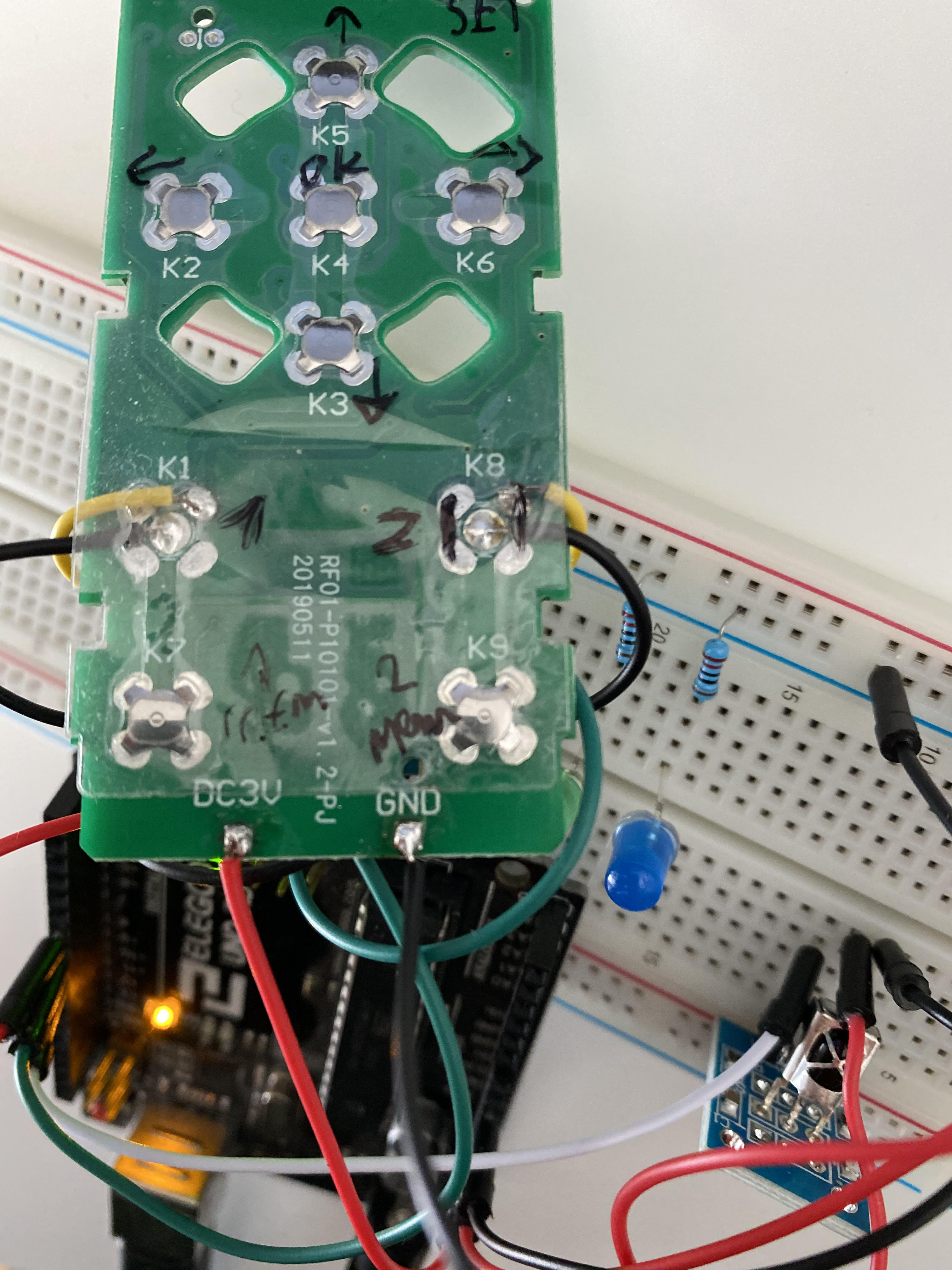
thanks for your support (honorable mention: DrDiettrich), I managed to succeed with my little project :).
I will leave some more information here in case someone wants to do the same. All that remains is to make it a bit more tidy and small and to hook it on the TV USB.
When you search for your next project, replace the Uno by an Arduino Pro Mini. Fits into a match box, battery power from the remote, a handy expansion to your RF remote freeing your Uno for further experiments

