Hello,
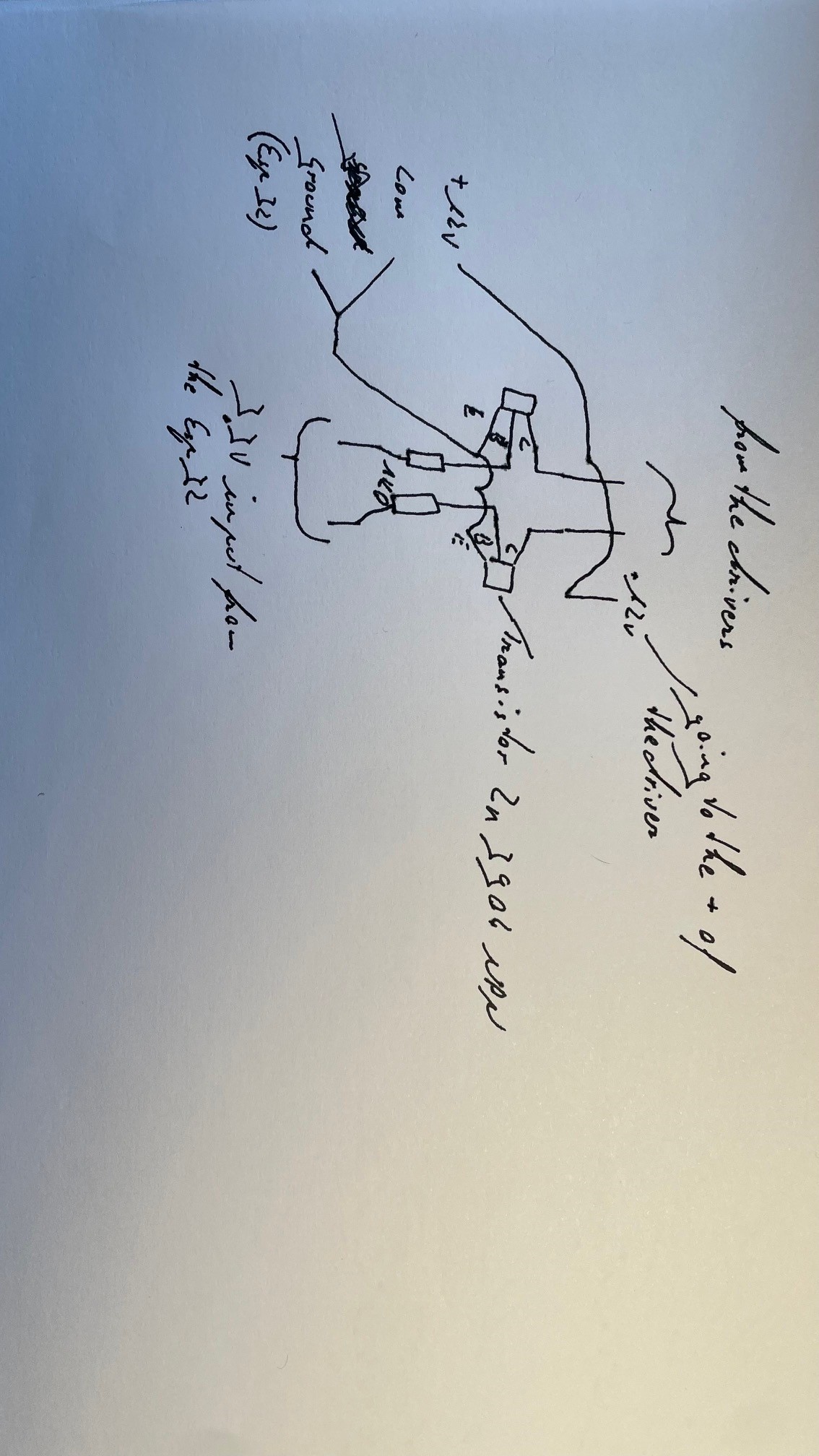
I'm currently working on a large 3d printed 6dof robotic arm. I'm using Nema 23 stepper motors and DM556Y stepper motor drivers and an Esp32. My Esp32 can only output 3.3V but my drivers need a voltage of at least 5V. To compensate for this problem I trigger a transistor to close a 12V circuit to do 1 step. As I want to drive 6 steppers I need 12 transistor circuits (6 * step and dir). I therefore made two soldered breadboards. During tests I noticed that no stepper motor could move. I investigate why this is. During my investigation I noticed that the 12V circuit to control step and dir are always on, which shouldn't be the case as long as the Esp32 doesn't trigger the transistor. I using my multimeter I noticed that the circuit is closed even though my Esp32 gives no output. Can anybody help me? Down below you can see some pictures of my self-made "PCB's" and circuit. If you need further explanation or information, please ask. I would be thankful if someone can identify y problem and suggests a solution. Thank You!
Why? The used stepper driver has optocoupler inputs with 10mA input current. It should be easy to drive them with a small junction transistor ( if connected correctly ).
@jacobutermoehlen : please provide a correct schematic how you connected the ESP with the DM556Y inputs. Your sketch does not really show the connections. And what type of transistors are you using?
Yes, the controller is current driven while the op is measuring voltages. The documentation shows "Logic Signal Current: 7 - 15mA(Typical 10mA)" . No mention of voltages.
If you use 12V, then there should be a current limiting resistor between the driver - (minus) the the transistor collector.
If not you will damage the driver
Thank you for your suggestion. I now have changed my power supply. I still have the same issue, the transistors seem to be opened and the circuit is closed ( I used my multimeter to check), therefore the step and dir pins are always open no matter the input of my esp32.
Well lets see if the transistors are good.
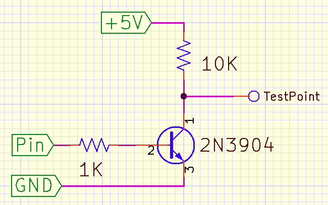
Disconnect one of the transistors from the DR- (or PU-) connection.
Connect a 10K resistor between the transistor collector and 5V
The voltage at the collector should be 5V with the Pin input LOW (0V) and about 0V when the Pin input is HIGH (3.3V)
Thats not my problem. the problem is that eventhough my esp32 oitputs are low the transistors are triggered and the pul/dir circuit is alwas closed (5v), no matter the input.