Dear Mark and Dave,
To share my tests.
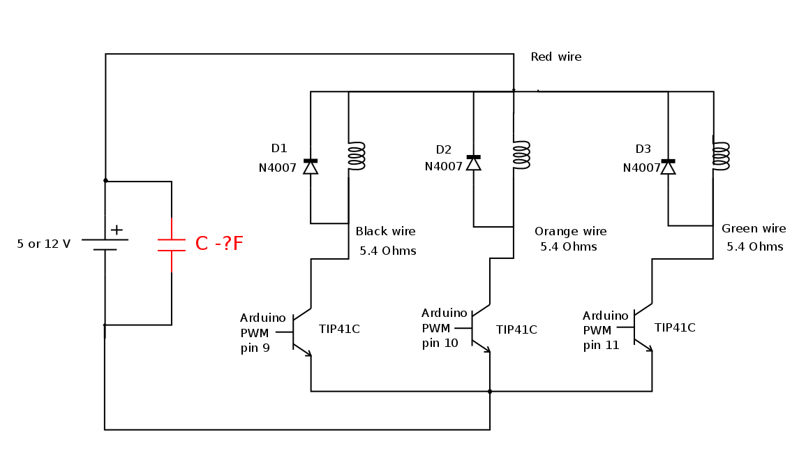
As I have the circuit on the breadboard with TIP41C I decided to do some measurements for my learning.
I did some measurements of base current (Ib), collector current (Ic), and the potential difference between the collector and emitter (Vce).
These measurements were made by applying 5 and 12 volts on the coils while maintaining 5V at the base of transistor TIP41C, because I intend to use the Arduino to apply current to the base of the transistor.
I observed that the higher the voltage applied to the collector, the greater the current that must be applied to the base to saturate the transistor.
For example, applying 12 V in the coil and 15 mA in base (Ib) of TIP41, the Vce = 4 V and Ic = 1.04 A, and the transistor becomes very hot.
But applying 5 V in the coil and the same 15 mA on the base (Ib) applies, the Vce drops 10x (Vce = 0.4 V) and Ic = 0.63 A). But in this case the transistor does not heat.
Measurements with 12V in coil and 5V in base
| Rb(Ohms) Ib (A) Ic (A) Vce (V) |
| 820 - - 9,7 |
| 507 - - 8,3 |
| 256 0,015 1,04 4 |
| 110 0,035 1,18 0,4 |
Measurements with 12V in coil and 5V in base
| Rb (Ohms) Ib (base current - A) Ic (colector current - A) Vce (V) |
| 500 0,008 0,5 1,5 |
| 256 0,015 0,63 0,4 |
| 109 0,035 0,65 0,18 |
I did these tests in only 1 coil and wanted to check the torque generated in the motor.
With 12 V torque is very strong, but the heating of the transistor is very high, moreover the Ic current is very high (1.04 A) and in the case of energizing 2 coils simultaneously
(Switched reluctance motor - Wikipedia), I would consume ~ 2 A and would exceed the limit of my power supply (1.5 a).
In the future I plan to use the Darlington and MOSFET transistors, but for now I'll test this circuit with TIP.
Thanks for the "TIPs",
Markos


