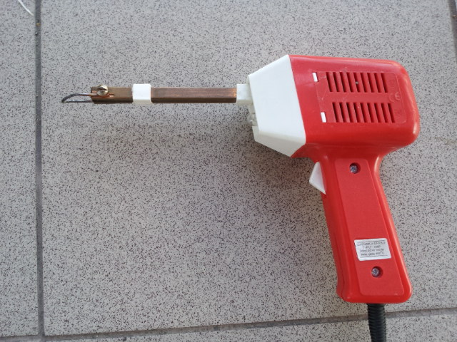
Hello, my soldering iron died 6 days after buying it >:( (KSGER T12 from banggood) so i want to make my own cause it seems like a fun project and isn't that complex
I didn't want to mess with charge pump and i only have N channel mosfets salvaged from a power supply currently, so remade the schematic and im interesting will this work with PWM ?
I need the mosfet to be fully on so heat dissipation will be minimal and i wont need to use a heatsink
sandorex:
I didn't want to mess with charge pump and I only have N channel mosfets salvaged from a power supply currently, so remade the schematic and I'm interesting will this work with PWM ?
Of course not!
sandorex:
I need the mosfet to be fully on so heat dissipation will be minimal and i wont need to use a heatsink
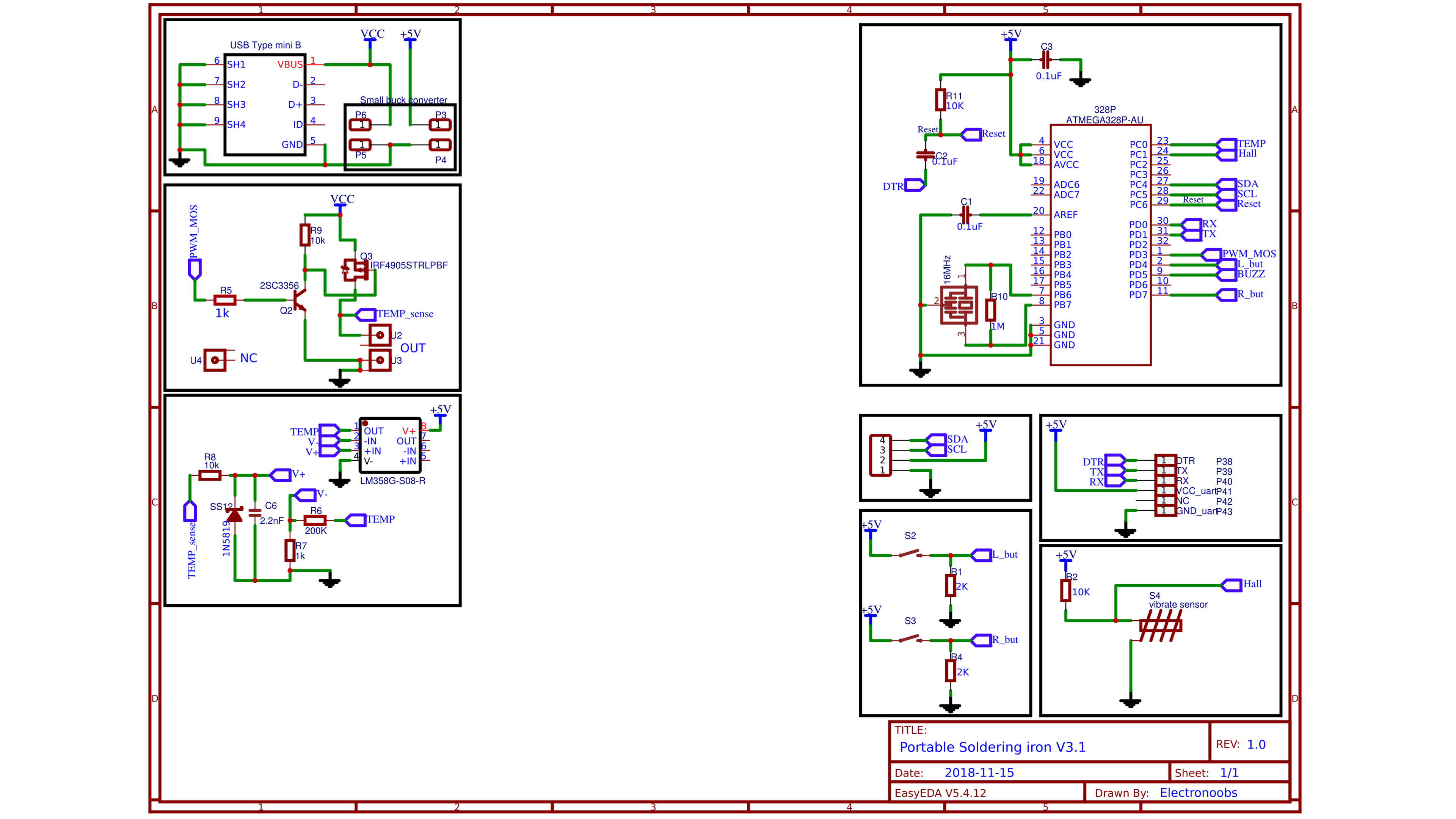
The electronoobs circuit from which you have copied uses a P-channel FET.
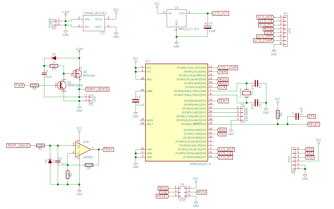
The second circuit from Jurgis shows a charge pump - it will generally work as long as the PWM value does not approach either 100% or zero - but is OK if the PWM is zero - switched off.
High side switching is generally done with P-channel mosfets.
That's an N-channel in your schematic:
Mosfet symbols
The electronoobs circuit from which you have copied uses a P-channel FET.
Yes unfortunately i do not have a P channel (mos)fet at hand, i will change the schematics when i get one, this is my only real iron the other one is the transformer one so i want to make it work
The second circuit from Jurgis shows a charge pump - it will generally work as long as the PWM value does not approach either 100% or zero - but is OK if the PWM is zero - switched off.
I honestly don't know much about charge pumps, but what i've seen from the simulations it doubles the voltage right?
In the simulations the Vgs with a charge pump exceeds 20V which is maximum for my mosfet (STP40NF03L), the simulation i've done, won't that damage the mosfet? should i add a zener maybe?
I was banging my head would it be possible to use the mosfet to switch the low side but i cannot think of a way of reading the PTC then, if you have some suggestions / solutions im all ears
You still believe this : ?
"cause it seems like a fun project and isn't that complex
I guess we have a different definition of 'fun':
"I was banging my head would it be possible to use the mosfet to switch the low side but i cannot think of a way of reading the PTC then, if you have some suggestions / solutions im all ears"
Where's the charge pump ?
"Yes unfortunately i do not have a P channel (mos)fet at hand"
Usually if you're going to make an omelette it's
kind of important to have eggs...
You still believe this : ?
"cause it seems like a fun project and isn't that complex
I guess we have a different definition of 'fun':
"I was banging my head would it be possible to use the mosfet to switch the low side but i cannot think of a way of reading the PTC then, if you have some suggestions / solutions im all ears"
Well it was more fun at first :), learning about mosfets but i still find it fun as im learning about opamps and things
I guess im just cheap cause i don't want to pay $3 shipping for couple of mosfets
sandorex:
In the simulations the Vgs with a charge pump exceeds 20V which is maximum for my mosfet (STP40NF03L), the simulation I've done, won't that damage the mosfet? should i add a Zener maybe?
That should reasonably take care of the VGS problem.


