I am making a DIY robotic arm that uses 4 servos to control it. I intend on using 4 potentiometers to control the servos. I have them all wired with the servos being run on an external power source. When I run my program in my software it works as intended. However, when I run it in real life wired the exact same way, it doesn't work. Occasionally one or two of potentiomiters will control a servo. Other times one potentiometer will control multiple servos. The majority of the time, 2-3 of the potentiometers will not move the servos at all. As well as these issues I am also having problems with servos stuttering. Any help with these issues would be greatly appreciated.
Your software likely has an infinite power supply. Your real life power supply needs to have at least 1 amp capacity for each servo. What are you using, now? You need to replace it.
Nope.
It brings you up with a link that asked you to sign up and get an account.
You will get help faster if you do not make potential helpers go off searching for your code and schematic. Read the forum guidelines to see how to properly post code and some information on how to get the most from this forum.
Use the IDE autoformat tool (ctrl-t or Tools, Auto format) before posting code in code tags.
Post the schematic here.
I am currently using 2 packs of 4 AA batteries run in parallel which should produce 6 volts and 6 amps of power.
Sorry about that. Here is the code:
// C++ code
//
#include <Servo.h>
const int Sensor1 = A0;

const int Sensor2 = A1;

const int Sensor3 = A2;

const int Sensor4 = A3;

int Base = 0;

int Gripper = 0;

int LeftArm = 0;

int RightArm = 0;

int Sensor1Min = 1023;

int Sensor1Max = 0;

int Sensor2Min = 1023;

int Sensor2Max = 0;

int Sensor3Min = 1023;

int Sensor3Max = 0;

int Sensor4Min = 1023;

int Sensor4Max = 0;

int count = 0;

Servo servo_2;

Servo servo_3;

Servo servo_4;

Servo servo_5;

void setup()
{
  servo_2.attach(2, 500, 2500);

  servo_3.attach(3, 500, 2500);

  servo_4.attach(4, 500, 2500);

  servo_5.attach(5, 500, 2500);

  pinMode(A0, INPUT);
  pinMode(A1, INPUT);
  pinMode(A2, INPUT);
  pinMode(A3, INPUT);

  while(millis() < 20000) {
  	Base = analogRead(Sensor1);
    if (Base > Sensor1Max) {
      Sensor1Max = Base;
    }
    if (Base < Sensor1Min) {
      Sensor1Min = Base;
    }
    Gripper = analogRead(Sensor2);
    if (Gripper > Sensor2Max) {
      Sensor2Max = Gripper;
    }
    if (Gripper < Sensor2Min) {
      Sensor2Min = Gripper;
    }
    LeftArm = analogRead(Sensor3);
    if (LeftArm > Sensor3Max) {
      Sensor3Max = LeftArm;
    }
    if (LeftArm < Sensor3Min) {
      Sensor3Min = LeftArm;
    }
    RightArm = analogRead(Sensor4);
    if (RightArm > Sensor4Max) {
      Sensor4Max = RightArm;
    }
    if (RightArm < Sensor4Min) {
      Sensor4Min = RightArm;
    }
    delay(50);
  }
}

void loop()
{
  Base = analogRead(Sensor1);
  Gripper = analogRead(Sensor2);
  LeftArm = analogRead(Sensor3);
  RightArm = analogRead(Sensor4);
  if (count == 0) {
    servo_2.write(90);
    servo_3.write(90);
    servo_4.write(90);
    servo_5.write(90);
    count = 1;
  }
  Base = map(Base, Sensor1Min, Sensor1Max, 0, 180);
  Gripper = map(Gripper, Sensor2Min, Sensor2Max, 0, 180);
  LeftArm = map(LeftArm, Sensor3Min, Sensor3Max, 0, 180);
  RightArm = map(RightArm, Sensor4Min, Sensor4Max, 0, 180);
  servo_2.write((RightArm - RightArm % 1));
  servo_3.write((LeftArm - LeftArm % 1));
  servo_4.write((Gripper - Gripper % 1));
  servo_5.write((Base - Base % 1));
  delay(10); // Delay a little bit to improve simulation performance
}
And here is a picture of my wiring diagram:
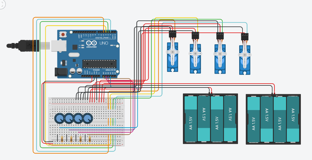
Breadboard isn't capable of handling large current. Power to the servos should be direct.
Ok, thanks for the suggestion. I will try that as soon as I can.
I rewired without the power running through the breadboard and it still didn't work. Any other ideas are greatly appreciated and I will try them as soon as I can. I also tried wiring in some capacitors and here is my wiring diagram for that.

This works well in the simulation, however it results in zero servos working.
Servo problems are almost always power related. Can you get one working with your battery packs directly powering it? Don't forget to connect the grounds.
I will test again with brand new servos incase it was somehow a problem with the servos. I'll repost later today with that result.
Why is there a resistor in the top leg of the pot? This will limit the range of readings the pot will give depending on the resistance of the pot itself. When using pots on an Arduino they should ideally be 10K.
Thank you, I will definitely try that also.
I have tried all of the solutions suggested and my circuit still doesn't work as intended. I got it to the point where it was working as intended for about 45 seconds. However all of a sudden, one potentiometer starts controling 2 servos instead of one and the other potentiometer stops doing anything. I have triple checked all of my wiring and nothing seems off. Any suggestions are greatly appreciated.
Then there are some intermittent connections in your bread board layout and they are not making good enough contact.
Please post a photograph of your setup.
Ignoring the pots, can you simply sweep each servo in turn to verify that you can control them?
Nasty case of space-itis there!
Just curious, but what is the point of that?
You then have the arm being controlled manually. You could just as easily use four "servo testers" to do that.

Mind you, I do believe these actually incorporate a small microcontroller themselves. ![]()
I'm using components that I already have on hand.
I just rewired the whole thing and had it working for a few minutes. I will confirm it is still working in a few minutes when I get back to my project.
If it works for a random period of time and then fails, and you are not using "String"s in your code, then it is/ was clearly a wiring problem.
1 Like