I'm new to Arduino and I need some guidance on my project. My project is about controlling the speed of DC motor with encoder and its angle of rotation using potentiometers.
Project Description:
The project is about controlling the speed and also its angle to which the motor should oscillate back and forth to the set angle and speed. Two potentiometers are used, one for speed and the other for the angle.
Project Parts:
HD Hex motor (REV-41-1391)
Two potentiometers
L298N motor Driver
Arduino Mega 2560
Hope to get some help on the steps on how to achieve this
I have achieved my first objective of the project which is to control the speed using potentiometers. However, I am not able to control the angle of rotation.
Any help will be appreciated
Below is the code for controlling the speed:
//Speed Control Using Potentiometer//
int input1 = 52;
int input2 = 53;
int PWM = 11;
int speed1;
int speed_1;

void setup() {
  Serial.begin(9600);
  pinMode(52, OUTPUT);
  pinMode(53, OUTPUT);
  pinMode(9, OUTPUT);
}

void clockwise(){
  digitalWrite(input1, LOW);
  digitalWrite(input2, HIGH);
}

void anticlockwise(){
  digitalWrite(input1, HIGH);
  digitalWrite(input2, LOW);
}

void loop() {
  clockwise();
  speed_1 = analogRead(A0);
  speed1 = map(speed_1, 0, 1023, 0, 255);
  analogWrite(PWM, speed1);
  Serial.println("Pot value = ");
  Serial.print(speed_1 );
  Serial.println("PWM = ");
  Serial.print(speed1 );
}
Thank you for the feedback :). I will improve on the variable names :).
For your information, I do not have the circuit diagram because I am building this project from scratch. Therefore, I am building and testing little by little and hence I do not have a fixed circuit diagram for this.
This is the parts I'm using:
HD Hex motor (REV-41-1391)
Two potentiometers
L298N motor Driver
Arduino Mega 2560
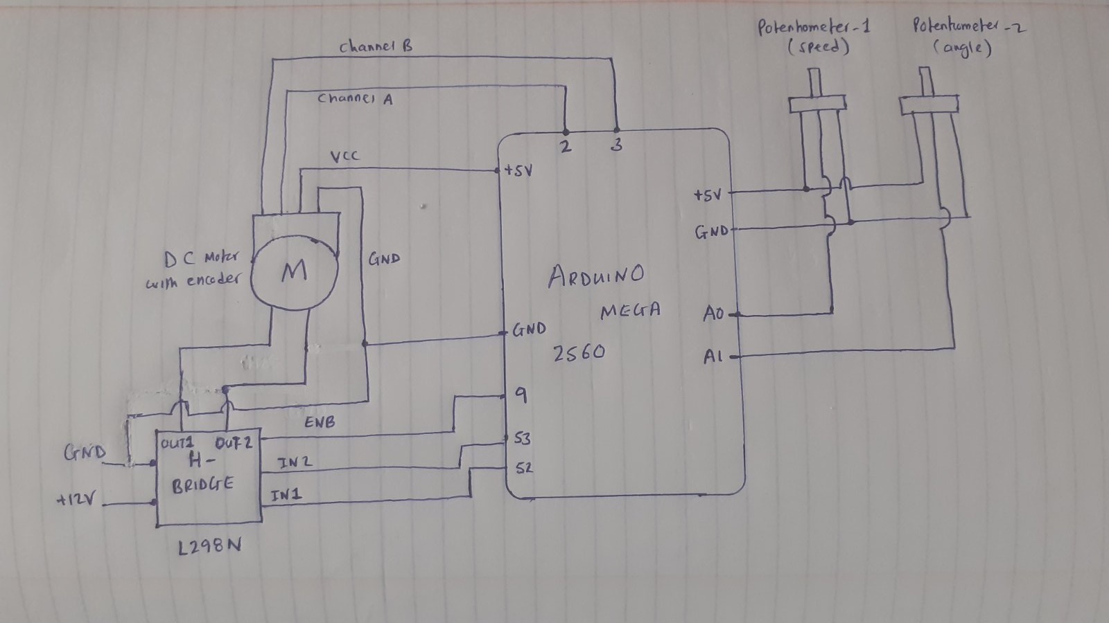
To control and power the motor I am using the L298N motor driver. From this particular driver, I have one pin connected to pin 52 of Arduino and the other pin of the driver to pin 53 of Arduino these pins are used to control the direction of rotation of the motor shaft. One pin from the L298N driver goes into pin 11 of Arduino which is for PWM. The motor positive and negative are connected to the dedicated connectors on the driver. The driver is powered up using a power supply which is set to 12V. The negative of the power supply is also connected to the common ground of the circuit.
The motor I am using has an encoder with it. Channel A and channel B of the encoder are connected to interrupt pin 2 and 3 of Arduino respectively. The encoder Vcc is connected to 5V from Arduino and the encoder ground is connected to the common ground of the circuit
For the potentiometers, one is connected to pin A0 to control the speed and the other to pin A1 to control the angle.
Hope this information has given you a fair idea about the connections.
For the circuit, a pencil and paper are usually good enough.
Take a pic and post it here.
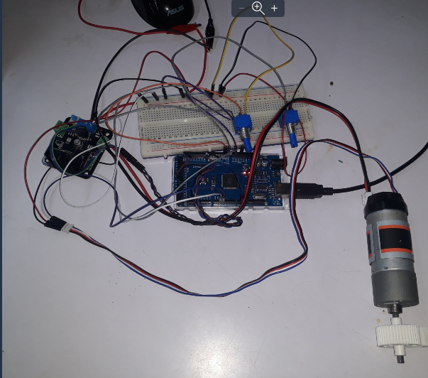
While you are at it, snap a few pics of your project as well. That often helps us understand what you are doing.
Thanks for helpful feedback :). Till today I am able to vary the speed using a potentiometer and also I am able to count pulses from one of the channels.
I need help on how to set the angle of rotation (0deg to 360deg). using the other potentiometer and make the motor shaft rotate back and forth in that particular set angle using the potentiometer. Also, I should be able to vary the speed using the potentiometer connected to A0 anytime. This condition also applies to the setting of angle rotation.
I need help on how to set the angle of rotation (0deg to 360deg). using the other potentiometer and make the motor shaft rotate back and forth in that particular set angle using the potentiometer.
Forget about the potentiometer to get started. How may counts per revolution is your encoder reading showing? Make the motor rotate back and forth 180 degrees
by using the value of counts/revolution divided by 2.
Home position will be a major issue. What is your thinking about that?
I have attached the hand-drawn the circuit diagram as requested :).
Does not your current code do that?
Yes with the current code I am able to vary the speed :).
How may counts per revolution is your encoder reading showing?
The following are the specifications of the motor:
Gear Ratio - 40:1
Free Speed (RPM) - 150
Cycles per Rotation of the Encoder Shaft - 28 (7 Rises of Channel A)
Counts per Rotation of the Output Shaft - 1120 (280 Rises of Channel A)
Home position will be a major issue. What is your thinking about that?
No idea about this
Forget about the potentiometer to get started. How may counts per revolution is your encoder reading showing? Make the motor rotate back and forth 180 degrees
by using the value of counts/revolution divided by 2.
Hi,
Why have you got one side of the motor and Out2 to gnd, when the 298 is designed to take both motor wires so it can control direction?
Your current circuit cannot change the motors direction.
Are you using a 298 IC or a shield/module?
Why have you got one side of the motor and Out2 to gnd, when the 298 is designed to take both motor wires so it can control direction?
Your current circuit cannot change the motors direction.
I had wondered about disappearance of anticlockwise() from the code
There are many tutorials about the use of the LN298. Here's a pretty good one