Follow the advice in Post #19 and take look at this simple PNP circuit.

Elaborating on the concept of "complementary transistors", there are sometimes available PNP and NPN transistors with very similar electrical characteristics with respect to voltage/current and gain ratings that are used together in a circuit like below.

Realize that this is a sort of pseudo-circuit that illustrates how you would connect the output to either side of the battery.
It's not necessarily useful in your project but illustrates how you might use the BD135/136 complementary transistor pair.
this is what i got;
this is just a small part of the scematics you just saw!
now for R1 and R2, i saw some people say that white leds ussualy draw 50mA and that for 1 led 220ohm is good. (that will be different because i have 8 in parralel.
and for R1 i dont know. this is what i found for the datasheet of the transistor but i do not know what to look at in order to find the base current draw. (because that is what i need right? because with that i can find the right resistance that makes it at least 0,7V lower than 3.3V)
*edit
for R1 could i just put a diode inbetween that will work right?
You are making progress. If you look at the data sheet for your LEDs you'll no doubt see that 3.3V is not going to be a high enough voltage to drive the LEDs since you will lose some voltage across the transistor and the resistor.
Also note that this is the correct way to use LEDs in parallel.

I'm off to work the phone banks to get people out to vote but I'm sure there will be other helpers here since you are working hard to learn.
i also have access to other voltages that are higher so the voltage is no problem.
i have 5V, 6V and 3cells of Li-ion in series from wich i can tap power.
yes great, i already had them wired in parralel but why not 1 resistor infront of all?
power gets distributed evenly in parralel and with cheap resistors that may vary a little (maybe to little idk)
for the datasheet, i dont have that, i got these leds at school and they buy then from china so i have no clue what type these exactly are. All i know is that they emmit white and are 5mm thick.
i did power one at 3.3v once and that seemd to work fine but idk with the resitors in place
It's called current hogging.
if I use 5V, i want a 1.7V drop for 3.3v
i looked at 4 different datasheets of 5mm white leds and 3/4 said 20mA and 1 said 30mA
if i use 20mA wich is likely to be the case i will need R=U/I = 1.7V/20mA = 85ohm resistor
and if it is 30mA i will need 57ohm but that is lower so that will mean no harm will be done if i use a higher resistor
i have 4, pair leds, is it ok if i use 1 resistor for every pair? or will that already be a problem?
You cannot use 5V
No... that creates another issue (related to why an NPN circuit is usually preferred):
In order to turn OFF the transistor, Vbe needs to be zero. If there is 5V on the emitter you need 5V on the base, and the ESP only puts-out 3.3V.
With the standard NPN switch/driver circuit the emitter is connected to ground so zero volts turns it off and it takes less than 1V to turn it on.
That's not a problem. Resistors have a specified tolerance (the allowable variation from the nominal value). 5% (gold if color-coded) is the most common and that's not going to make a noticeable difference in brightness. Occasionally you'll run-across a 10% resistor. I've heard of 20% resistors but as far as I know they don't make them anymore.
Everything in electronics has tolerances... (When we're working with digital we don't care as long as a "1" remains a "1" and a "0" remains a "0".)
One of the pair MAY be brighter than the other but it should be OK. Just remember that you need double the current, so half the resistor value.
If you were making a "product design" a separate resistor for each LED is "correct". Resistors are cheap and if space is important you can use surface mount components so there's no reason not to do it the right way.
please tell me why?
because when you say no, i would like to know why otherwise i won't learn ![]()
@DVDdoug explains it in post #29
ah i see, so i will still use the same 3.3V output as earlier, but what about the resistance how do i calculate that now? what voltage do i need to operate the leds at?
Because if i used 5V in my calculations this will be of no use when my supply is 3.3V. what operating voltage do i need to use?
I would suggest you use an NPN transistor and switch the ground side of your resistor/LED circuit. Then you have more options for a LED power source. The PNP transistor you have selected doesn't have enough gain to switch your LEDs with the base current safely available from the ESP.
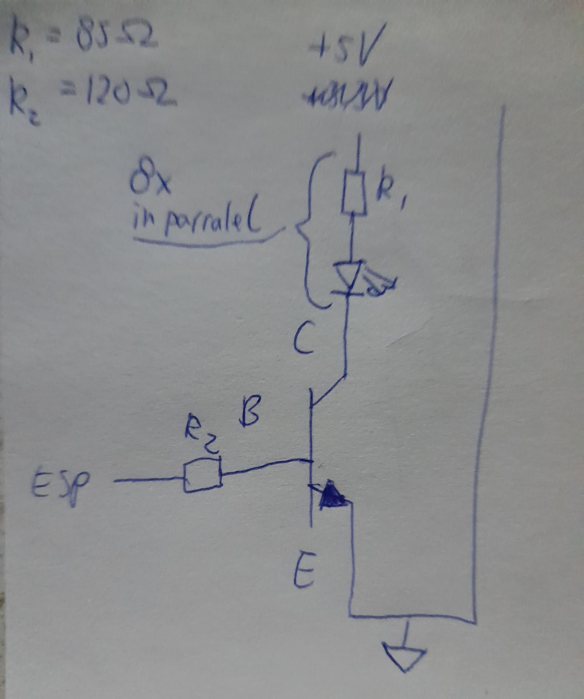
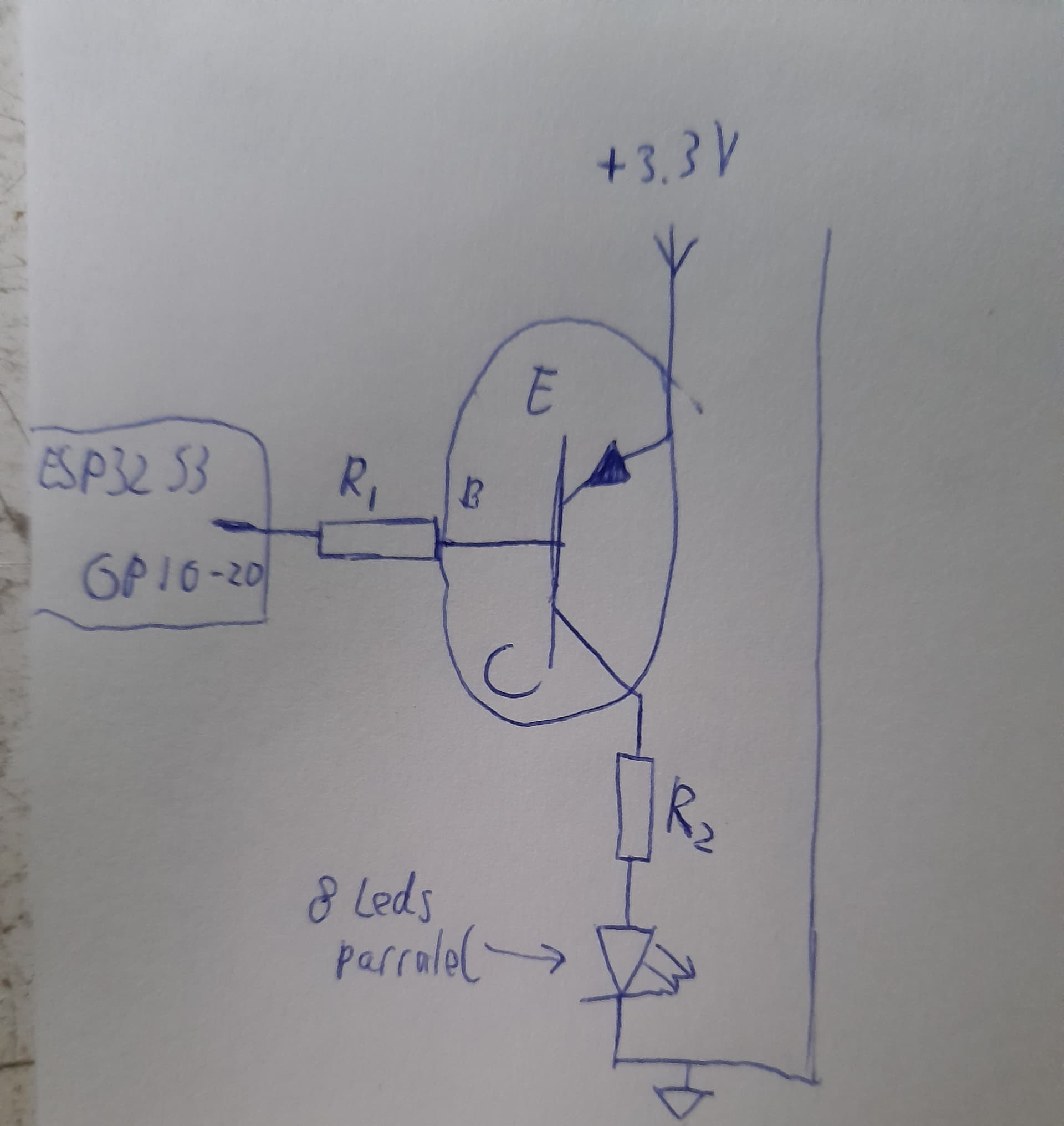
i just saw that i also have the BD135 a NPN. do i wire it like this then?

ugly sketch i know
i am finding different images with different collector and emitter arrows and orientations on the internet for the same transistor and i dont know wich one to take
Instead of 3V, connect R1 to 5V.
so for a NPN that is ok?
Probably, considering the LED current you will be using and the typical gain of that transistor. The higher the LED drive voltage, the better the chances of working. I'm too busy to look up the ESP drive current but if you design for 0.01A you will not damage it and that will probably produce enough LED current.
drive current is by standard 20mA and can be raised to 40mA.
so for the Base i can do R2 = U/I 0.8V/40mA = 20ohms
or not?? i am a bit confused atm
I'd stick with 20mA.
Vbe Max for the transistor is 1V so
3.3 - 1 is the voltage drop across R2.
2.3 / 0.02 = 115 Ohm so 100R or 120R would be okay