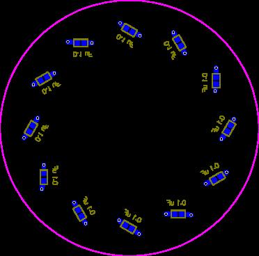
Well I hope I have come to the correct place to ask this question. I have designed a PCB that incorporates 12 WS2812b chips and a TCRT5000(ir sensor). All of this is connected to an Arduino and the pattern on the LEDs are controlled by the input information of the IR Sensor.
I have looked these over and over and over and I think I have all the connections made how they need to be in order to get this to operate, the question I have though is the incorporation of a 0.1 uF MLCC capacitor with vias. The capacitors are on the bottom layer and connected directly to the ground and V+ with a via from the top layer under each LED.
I have included 3 jpgs of the circuit. One shows the silkscreen and top copper area, one shows the silkscreen and bottom copper area, and one shows the top silkscreen and top and bottom copper area.
Is this the correct way to connect these capacitors?
Also, aside from that, if anyone have more knowledge (wouldn't take too much), how does the rest of the circuit look? I will be having a bunch of these printed, but before I send the order off, I want to see if all looks good.
Grump_Mike thanks for the input here! I will get a schematic drawn up today and post it on this thread as well. I put this together using a few different schematics as reference, but have not yet made a schematic of this design.
You need to make a schematic before you can lay anything out. Trying to do without one is silly and will lead to errors that no one can spot because the schematic is in your head.
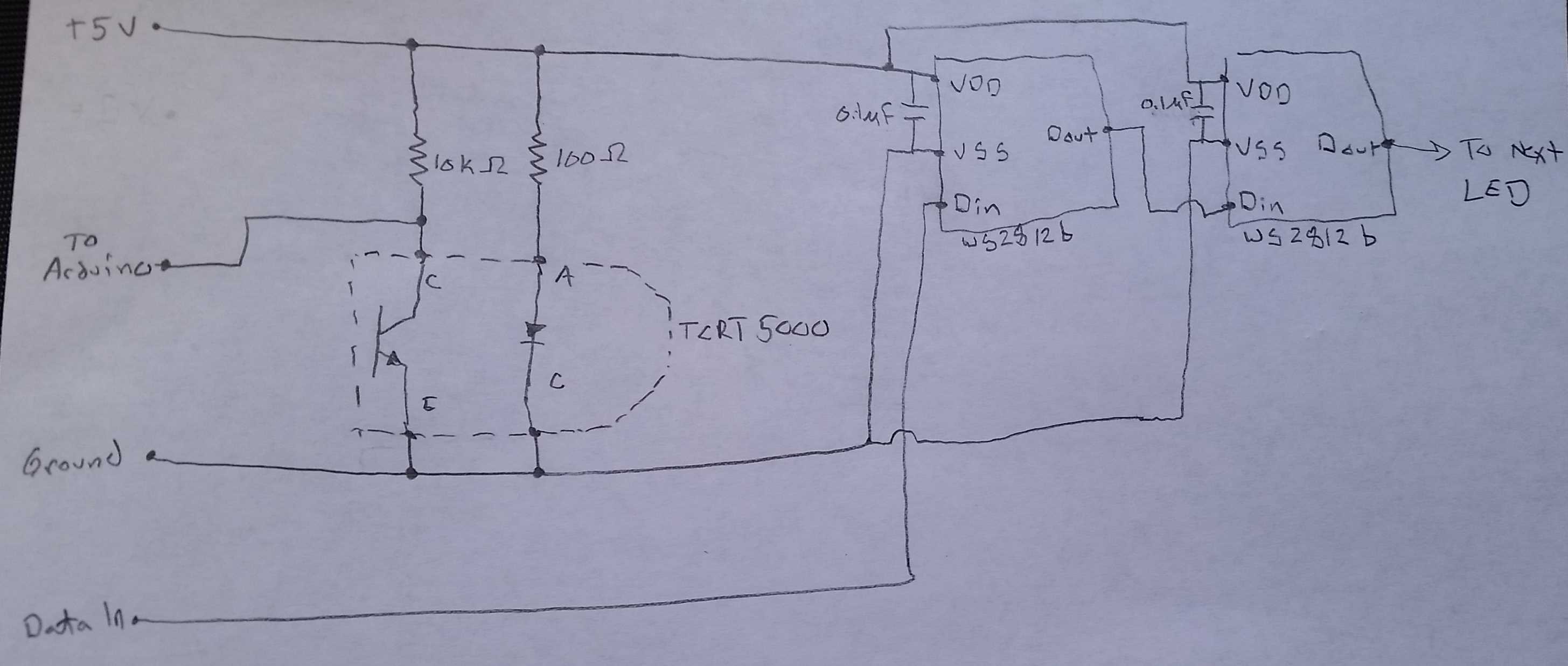
I have drawn up a schematic, rather crude, but followable. It shows the connections made on the PCB in a straight layout and not the curved layout. I have only included 2 LEDs, but it will follow the same connection pattern to all 12.
The circuit uses a TCRT5000 to read the IR light above the pod. The signal (to arduino) is then sent to the Arduino, then the code spits out a signal that goes to the WS2812b LEDs based on the IR light input (data in).
Hopefully the schematic can help "decode" the layout I have in the PCB design.
Also, there are 6 pads on the PCB. 1 is IR out, one is data in, 2 are V+(in and out) and 2 are ground (in and out). These 6 pads will be single row headers mounted in the board.
Sorry, the attachment was too large and did not attach to the post. It made me wait to make the revised post because it tells me I am "exceeding the number of posts I can make in a 5 min period." Sure glad this thing is being cooperative with me today.....
I got the breadboard out and played with the resistor value there. I am simply using the "pods," as I call them, to detect if an object is very close directly over the top of it, and do not need much distance or it will falsely trigger the change in LED pattern.
I will have these pods mounted in a table, under a thin sheet of plexiglass that is sealed in to the table with clear epoxy, so I am apprehensive to make it too sensitive because it may cause the LED pattern to change even without an object on top of it.
I am pretty sure I tested a 100K there, but may break the breadboard out again and give it a try anyway, just to see the changes to the values.
I do not plan to use a ground plane per say. Each of the pods will have a ground in and each LED will have it's own capacitor. All of the pods will have 5V and ground run to them using an "in" and "out" set of pins. All 20 pods and the Arduino will be connected to the same 5V and ground source. May also run this with 2 Arduinos, and use 1 for each group of 10 pods.
I plan to use a 5V 2A power source, but may have to bump that up to account for all the components of the circuit.