Current distribution in a simple motor drivers circuit

Circuit:


DC power supply bench voltage feeds 3 TMC2208 stepper motor drivers, each driving a NEMA 17 stepper motor, 100uF 35V elecrolytic capacitor in parallel with each. 5V regulator to power a teensy 4.1 board which control the logic for the motor drivers.

The TMC2208 motor drivers came with the factory with the following Vrefs: 1.54V, 1.55V, 1.56V, which through the formula from its datasheet: I_RMS = 325/(110+30)(1/sqrt(2))(1/2.5)*Vref correspond to a current limit that is passed to the motor of I_RMS = 1.01A, 1.02A, 1.03A respectively.

According to datasheets:
TMC2208: rated current 1.2A , Max current 2.0A
NEMA 17 of the model I got: rated current 1.68A, max current 2A

In a basic test, the circuit functioned well, rotating all three motors as programmed, using AccelStepper arduino library and set to some max speed. In this test, the teensy drew around 200mA.

In the operational code, the program on the MCU reacts to readings from a touchscreen that balances a steel ball, and commands stepper motor rotations accordingly.

Issue:
I was stupid enough to now run the operational code with the DC supply workbench set to 5.0A current limit (voltage is 16V, I plan on increasing to 24V). After about 1 sec of operation, one of the TMC2208 got severely damaged. Its GND and MS1 shortened, which of course leads to shut down of the MCU. My assumption is that it had too high of a current pass through this motor driver, that damaged it.
To my understanding, I_RMS above is the RMS current the driver will try to deliver to the motor phases, not necessarily the current that actually passes through the driver itself. So the fact that the drivers came from the factory set to I_RMS values of ~1A has nothing to do with the current that they actually draw themselves. In order to burn the motor driver, which actually occurred, the current passed through it had to be higher than its rated 1.2A, possibly much higher.

Question:
Can / should I limit current I1, I2, I3 in the figure above? If the figure isn't showing, those are the currents to each of the motor drivers. The limit I can set in the supply bench is for I_total. I_MCU is ~200mV so it's not in the focus of the question.

Even if theoretically I limited I_tot to as low as 1.7A, the program may assign stepping commands that require nothing out of 2 of the three motors, but max out of 1 motor, which may still lead to the damaging of its driver. I'm starting to run out of motor drivers to burn. Will setting the total current limit to 1+1+1+0.2 =~ 3.5A be enough, hoping that all 3 of them will draw currents in a close to 1:1:1 ratio? or should I add some mean of current limitation to the individual motor drivers? If so, how? As I described few lines above, they may receive commands from the MCU in an unpredictable x:y:z ratio.

  • I'm following instructions from from this instructables page, where ~10 other people have made this mini project work without additional current limiting circuitry.

Sounds like wiring error, not that you were drawing too much current to the motor.

Thanks for your comment. All wirings were exactly as shown above. I checked many times..

Only you can verify them, using your multimeter. inspect for any solder bridges/cold solders as well.
I'm repeating, it's very unlikely your driver makes suicide in one second because of high motor current.

Thanks, I'll try to explain myself better. I invested a lot of time in thoroughly checking all my soldering and wiring with my multimeter. I made sure there are no shortages countless times. I did all I could to verify that the wiring above is implemented exactly. The test program that rotates the motors worked well. It involved setting max speed to 200 and then steppers.moveTo(pos); commands and it executed successfully. The problem happened when I first connected the touch panel and used the author's code, which both seem to work for him as well as for others at the bottom of the instructables page

So focus there, what changes you made.

The changes I made were:

  1. Connecting the touch panel to the A0-A3 pins of the teensy
  2. Changing the current limit on my DC power supply bench to 5A
  • I'm not sure it wasn't already set this way during the test program, which uses setMaxSpeed(200);
  1. Using author's code

Then I put the steel ball on the touch panel, it did some rotating for roughly a sec +-, teensy shuts down. Then I looked into it and found out that one of the stepper motor drivers got its GND and MS1 shortened together :slight_smile:

That is because it is not needed.

Setting a current limit on the power supply will not save your drivers from burning out.
Did you have the heatsinks on the boards?

I see in the schematic that the 5V regulator is designed wrong. There should be capacitors on the input and output of the regulator. Without them the output colud become unstable

Yes

The guide doesn't mention capacitors on the voltage regulator, maybe its missing them. So the malfunction that caused damage to the motor driver came from the teensy board? What capacitors and how should I position them?

I keep a multimeter measuring the voltage on the output of the regulator, if there was a sudden surge I probably wouldn't have seen it the moment it happened. I've never seen it not my desired 5V, including when tested simple rotations with 16V supply and setMaxSpeed(200).

Thank you

If you already have 100uFs, then put one on the input and one on the output. The lack of capacitors may have caused the teensy to reset or freeze but not sure how the drivers would respond.

Your problem is more likely due to a bad solder joint or loose connection. You may not find them by checking with an ohmmeter.

Sorry, I see that the schematic shows a 78xx and a 24V battery but the website actually uses a buck, so no capacitors needed.

Your wiring image and proto-board image don't really match.
I wonder what would happen if you had flimsy GND connection to motor supply header. It would leave the only path through driver logic pins...

Thank you sir. I see what you meant with the 78XX. I'm using the buck converter they linked to.

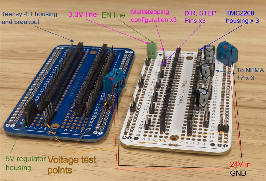
Regarding soldering, I did my best. I know it can't be pointed out from looking at a picture, but I'm adding them just to show. I spent a lot of time checking continuities with the multimeter, everything seems to be connected in the right way. The basic rotation tests went well.


In what way? If you're referring to the Vin and GND lines, I have them split by using anderson powerpole connectors. The split lines feed to each perfboard through its blue terminals

Sorry to tell, but doesn't look great soldering..

On your wiring "diagram" image if you disconnect main GND, everything turns off.
On your actual protoboard image if you disconnect motor supply GND, bad happens.

Well...
Have a look here

Lol yes I admit but this is the best I managed. I don't think that GND on the motor protoboard ever disconnects, GND on it still beeps continuity... even though the soldering isn't great

That may be true but with 3A going through it could be different. May be a high resistance or even intermittent
Have a look at the Adafruit link I provided.

But if soldering is not rock solid, tiny disconnections can occur from heatup or vibrations.

Also be aware these notes from one driver module supplier:

That's a good link

Thank you for your answers and comments. Bottom line, do you really think that the problem is in the soldering? I'm not ruling it out, I just want to make sure. Please if you may, download the pictures I uploaded, zoom in and tell me that you really think it might actually be the problem. When I ran the basic tests to rotate all 3 of them together it drew more than 2 amps for sure...

Other than that, do you have any other ideas? I'm doing 1:1 what the guide says, the only thing that I thought I might be doing wrong is not setting current limits right