I tried a lot to fix a little problem in my project (for hours) and still no luck.
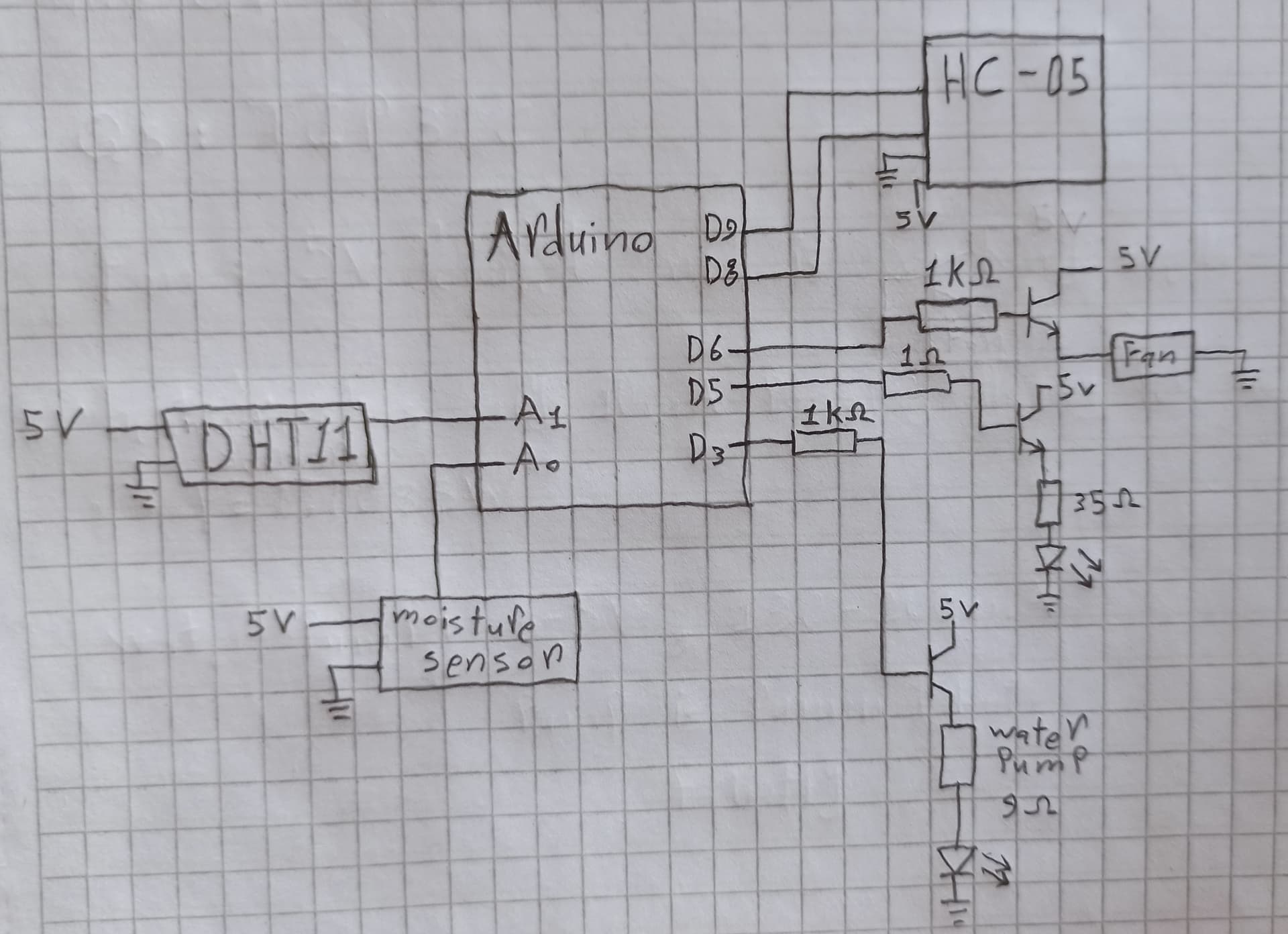
Basically, I wanted to make a heater that has 35Ω resistance (I also tried 6Ω), I connected the Arduino pin 5 to a TIP31c transistor to amplify the current.
But the only current I am getting is 12
mA, sometimes 20mA, so there must be something wrong.
I tried a 2N2222A transistor before that, I also tried increasing the base resistance to 1000Ω, and tried decreasing it to 1Ω, still did not help getting the result I was hoping for.
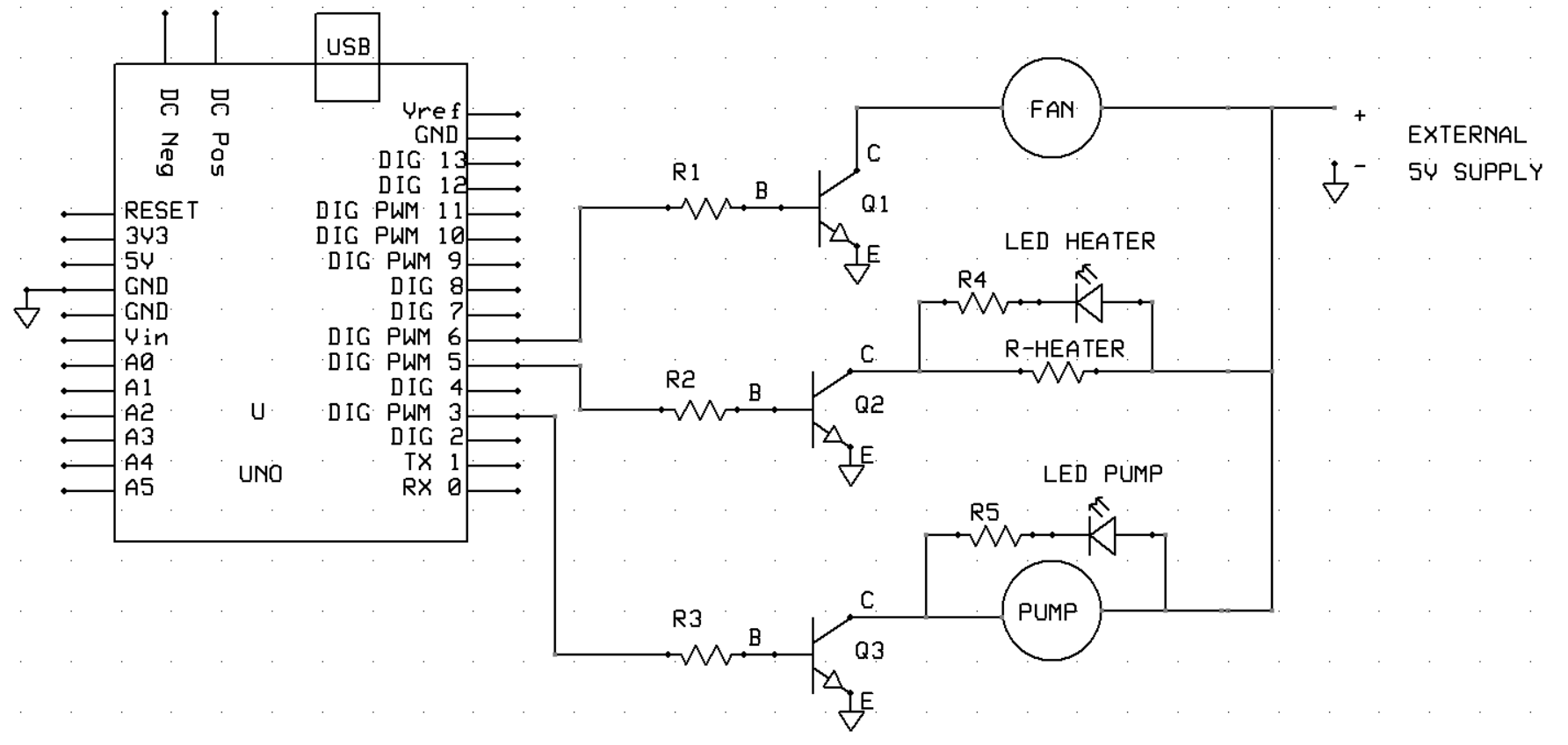
Here are images for schematics I drawn for the heater circuit, and the Arduino circuit, I hope you can help me, thank you!
To add to what @Railroader said, you have a voltage follower, the voltage on the emitter will follow the voltage on the base, minus about 0.7V base emitter voltage. The problem is made worse by the (unnecessary) diode, which reduces the voltage by another 0.7V.
The base resistor should be about 220Ohms, 1 Ohm is way too low.
The Arduiono board is not a power source. The tiny strips are made for some milliamps only.
9 volt battery? A PP3? Put it back in the fire alarm, remote or where ever it comes from.
Please post schematics showing the powering of the build. Your reply indicate severe mistakes.
Connect the load (fan, pump, etc.) between 5V and the transistor's collector like TomGeorge shows.
Good. "Regular" LEDs work at about 20mA or less. The same current flows through all series components so the pump current is too much. Plus there is about 2V dropped across the LED so the pump is getting less voltage (and the total current is less than expected, but possibly too much for the LED).
Emitter followers will never work. You must have the load in the collector line.
And the base current must at least be 5% of the collector current (10% for a TIP31).
NPN transistors won't work for loads larger than a few hundred mA, because the Arduino can't supply enough base current. Not enough base current means that the transistor is not fully saturated, will get hot, and could fail.
A 1k base resistor delivers 5volt - 0.7volt BE junction loss = 4.3 / 1k = 4.3mA.
In theory only good for switching 43mA with a TIP31 or 86mA with a 2N2222.
A 220 ohm base resistor will do a bit better, but still falls short for the loads you're switching.
Logic level mosfets are needed for loads larger than ~400mA.
Leo..