Wawa:
Are we still talking about the diagram from post#10, with the LM358.
? ? ?

I think we need an updated circuit?
Shouldn't you have a 1K in series with pin3?
Where are the resistors you are talking about?
Thanks.. Tom.. ![]()
Wawa:
Are we still talking about the diagram from post#10, with the LM358.
? ? ?
Where are the resistors you are talking about?
Thanks.. Tom.. ![]()
Post # 32
ted:
Post # 32
Okay, what OP-Amp?

Tom.... ![]()
LM358
Hi,
Okay.
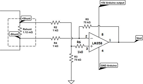
I think you will find if you put R6 in circuit, it may perform better.
Operational Amplifiers operate in neg feedback mode by trying to establish a Virtual Gnd at its inputs.
Have you grounded the other two inputs of the LM358?
Tom... ![]()
R6 - maybe, grounding maybe also.
OP has another problem, I think he is using not isolated power supply for load and for op amp, probably common ground, so complete circuit is limping
Hi,
Yes, not sure, will readup, but I don't think the LM358 are keen to behave when the inputs are near signal gnd.
R6 I've added may help, you will have to suck it and see..
Tom.. ![]()
Hi,
Some interesting reading;
And from the LM358 TI spec/apps;
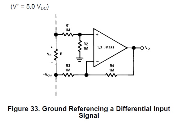
That is acting as a unity gain buffer, so then add an amplifying stage.
An instrumentation amp would probably be best, but if we don't experiment..
Tom.. ![]()
Post # 65 - ground problem.
Post # 45 = post # 66 = post #47 and # 50.
Post # 66 - I cut ground connection between - Shunt lower end of resistor and C1. = Classic differential amplifier,
Hi
This is my circuit that I used from were TED posted it.
All the mods and measurements was done on this circuit.
With linear I mean when I draw 1A and get 1V output from the opamp.(not real figures just for example)
Then 2A drawn should give 2V output from the op amp.
This I dont get I will get almost 3V.
The above value only show that double the amps drawn does not give double the voltage output.
I always get a significant amount more than what was expected.
When the shunt is 0.1 ohm(1 resistor) the output is linear.
When 6 x 0.1 ohm in parallel is used for the shunt the output is far from linear.
Did anybody build this circuit with the same op amp and got it to work??
I will replace the op amp and re-test to see what happens.
You measure voltage between two points of isolated guy

Post # 59
Hi
TED..what is the multiplication value of your circuit with the 6V batt?
multiplication is not related to 6V, I put that so you can use 4 batteries 1.5V.
By theory multiplication should be 100 in practice is 10
Yes TED I know the 6V batt does not determing the gain.
I removed the shunt negative side from the op amp negative supply and used a separate batt to power the op amp.
15A gives 3.77V output , this is the max output (5V-1.2V) the opamp will give,1.2V below rail.
Seems like the gain is to high ,I replaced the 2 x 100k's with 2 x 10k.
The circuit is working as expected now.
15A = 0.21 V on shunt = 2.1V at op amp output pin.(x 10 amplified)
1A = 0.018V on shunt = 0.18V at op amp output.(x 10 amplified)
Thanks.
probably my resistors were 10k
Next time start with schematic so problem can be solved in 1 page not 6.
Hi
What software do you use to create all this nice circuits???
Thanks.