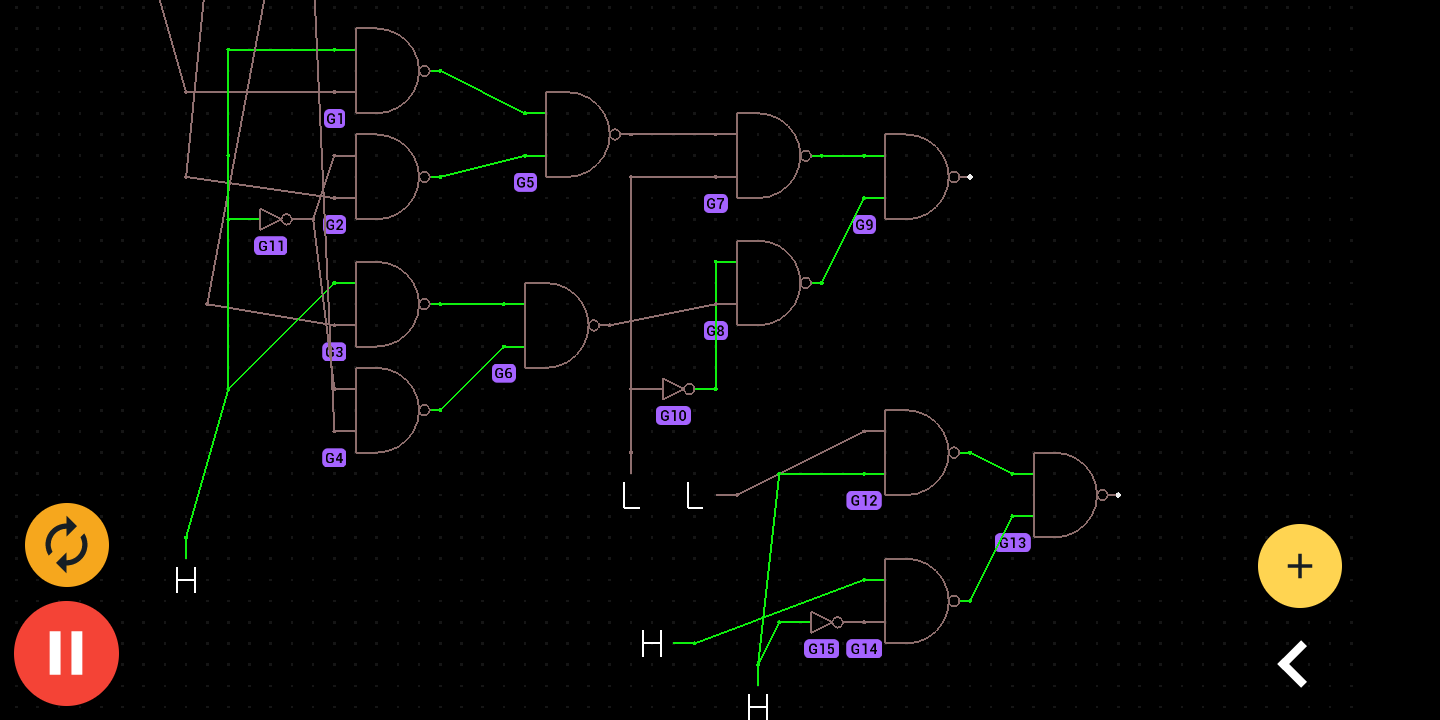
I builder the circuit that I already done in app Proto (I will provide a print screen) in thinkercad, but aren't working, it always brokes an component or give error in multimeter. Here's the thinkercad link
It happens to be the same circuit that I mentioned in this answer, but the subject is completely different. It's buggy in thinkercad and that's the topic
What do you mean by that?
That is to say, it is working in the simulation made in APP Proto, but it does not work in thinkercad. I just talked about this it this because I want to refer it in confident way
In the app PROTO I used for all inputs a component called Logic input . The input of that component is a bit. Maybe if I replace that component with one more identically I can more easily discover what is the bug.
Mas não sei bem qual o mais parecido.
The circuit is redone in an more similar way. I did it in two stages.In the first step I used one IC for each NAND gate and powered all iICs in series .In the second step to save ic I I used the maximum NAND gates of each IC as possible and powered all ICs in parallel. In the first stage the circuit worked, but in the second it no longer worked. So it still buggy, but now we know that we don't need any more component I think
As a test, I added 6 switches and an LED. The difference between the switches is the wire color.
I used two select bits with one the other color is to say, if it is to turn on the LED, or not. So that means maybe I made a mistake with the data connection. I have enough experience to build this circuit, after all I already built it in simulation and it worked, but I must have made a mistake in some connection, but I'm having difficulty finding the connection where I made a mistake.