Bonjour,
j'aimerais faire un projet qui me permettrais de savoir le taux de décibels en temps réel.
Je dispose d'un module ESP32.
J'aimerais quelque chose facile à mettre en place.
Quelle module pouvez vous me conseiller ?
j'en ai vu plein ![]() ,
,
j'avais vu MAX4466 mais je ne trouve pas de programme déjà fait qui affiche le taux en DB
Une petite recherche dans YouTube?
Ou Google?
Cordialement
jpbbricole
J'ai fait, justement ya pas grand chose la dessus ![]()
(159) Arduino Sound Meter - YouTube
j'avais vu ça mais c'est pas sur ESP32
t'en pense quoi du programme ?
//--------------------------------------------------------------------------------------------
 //                                       GLOBAL VARIABLES
 //--------------------------------------------------------------------------------------------

const int sampleWindow = 50;                              // Sample window width in mS (50 mS = 20Hz)
unsigned int sample;

 //--------------------------------------------------------------------------------------------
 //                                            SETUP
 //--------------------------------------------------------------------------------------------

void setup()
{
   Serial.begin(9600);                                    //Serial comms for debugging

}

//--------------------------------------------------------------------------------------------
 //                                         MAIN LOOP
 //--------------------------------------------------------------------------------------------

void loop()
{
   unsigned long startMillis= millis();                   // Start of sample window
   float peakToPeak = 0;                                  // peak-to-peak level

   unsigned int signalMax = 0;                            //minimum value
   unsigned int signalMin = 1024;                         //maximum value

                                                          // collect data for 50 mS
   while (millis() - startMillis < sampleWindow)
   {
      sample = analogRead(0);                             //get reading from microphone
      if (sample < 1024)                                  // toss out spurious readings
      {
         if (sample > signalMax)
         {
            signalMax = sample;                           // save just the max levels
         }
         else if (sample < signalMin)
         {
            signalMin = sample;                           // save just the min levels
         }
      }
   }
   peakToPeak = signalMax - signalMin;                    // max - min = peak-peak amplitude
   float db = map(peakToPeak,20,900,49.5,90);             //calibrate for deciBels
   Serial.print(db);                                     //write calibrated deciBels
   Serial.print(" dB");                                  //write units


}
Bonjour
Voir un exemple de réalisation içi sur ESP32 , avec pondération dbA (important pour ce qui me concerne !)
https://forum.arduino.cc/t/sonometre-connecte-esp32-micro-i2s/643771
Il ya juste le microphone sur bus I2S à ajouter à une carte quelconque à ESP32
Il ne s'agit d'une petite adaptation perso d'une excellente réalisation de ikostoski :
https://github.com/ikostoski/esp32-i2s-slm
Bonjour oasixm
Oui, l'habitude de rechercher pour Arduino, il fallait faire esp32 decibel meter.
Cordialemement
jpbbricole
Ok niquel, j'ai un ics-43434 ![]()
je vois qu'il est indiqué dans le github que tu as mis GitHub - ikostoski/esp32-i2s-slm: Sound Level Meter with ESP32 and I2S MEMS microphone.
Je ne comprend pas, sur quel port de mon esp32 je dois brancher mon ics 43434
1 ->ws sur port 32
2->LR sur GND
3->GND sur GND
4->SCK sur port 23
5->VDD sur 3.3v
6-> SD sur port 33
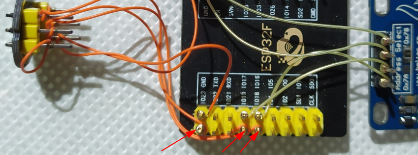
mon brochage est pas bon, j'ai repris le brochage de son ESP32, il ne devait pas avoir la même que moi, possible de m'aider , je dirai que SCK va sur 18 mais pour les autres voici mon pinmap :

l'ESP32 est souple pour le positionnment de certains signaux, dont ceux de l'I2S et de plus l3ESP32 possèède deux ports I2S. Les documents type 'pinout' sont en génaral incomplet et ne montrent que certaines possibilités.
dans mon cas le brochage est 18,19 et 23 :
//
// I2S pins - Can be routed to almost any (unused) ESP32 pin.
//            SD can be any pin, inlcuding input only pins (36-39).
//            SCK (i.e. BCLK) and WS (i.e. L/R CLK) must be output capable pins
//
// Below ones are just example for my board layout, put here the pins you will use
//
#define I2S_WS            18
#define I2S_SCK           23
#define I2S_SD            19

// I2S peripheral to use (0 or 1)
#define I2S_PORT          I2S_NUM_0
içi la version à afficheur OLED I2C:
j'utilise déjà mes port 18 , 19 , 23 pour mon écran TFT.
Tu connais les autres ports que je peux me mettre ?
Je vais enlever l'affichage oled, si je supprime dans le programme, ça devrait fonctionner
OUi, c'est écrit dans le commentaire du code :
/ I2S pins - Can be routed to almost any (unused) ESP32 pin.
//            SD can be any pin, inlcuding input only pins (36-39).
//            SCK (i.e. BCLK) and WS (i.e. L/R CLK) must be output capable pins
SD n'importe où, pour SCK et WS : tout GPIO disponible pouvant fonctionner en sortie
Voir ce qui est en vert dans la colonne Output de ce site :
https://randomnerdtutorials.com/esp32-pinout-reference-gpios/
ok si j'ai bien compris je peux donc faire ça :
#define I2S_WS            18 -> 4
#define I2S_SCK           23 -> 16
#define I2S_SD            19 -> 17
J'ai supprimé la partie oled dans le code, tu as un ics-43434 aussi ? toi
ça te dérengerait de tester si mon code fonctionne, il est cencé juste afficher les db dans la console.
#include <driver/i2s.h>
#include "sos-iir-filter.h"

//
// Configuration
//

#define LEQ_PERIOD        1           // second(s)
#define WEIGHTING         C_weighting // Also avaliable: 'C_weighting' or 'None' (Z_weighting)
#define LEQ_UNITS         "LAeq"      // customize based on above weighting used
#define DB_UNITS          "dBA"       // customize based on above weighting used
#define USE_DISPLAY       1

// NOTE: Some microphones require at least DC-Blocker filter
#define MIC_EQUALIZER     ICS43434    // See below for defined IIR filters or set to 'None' to disable
#define MIC_OFFSET_DB     3.0103      // Default offset (sine-wave RMS vs. dBFS). Modify this value for linear calibration

// Customize these values from microphone datasheet
#define MIC_SENSITIVITY   -26         // dBFS value expected at MIC_REF_DB (Sensitivity value from datasheet)
#define MIC_REF_DB        94.0        // Value at which point sensitivity is specified in datasheet (dB)
#define MIC_OVERLOAD_DB   116.0       // dB - Acoustic overload point
#define MIC_NOISE_DB      29          // dB - Noise floor
#define MIC_BITS          24          // valid number of bits in I2S data
#define MIC_CONVERT(s)    (s >> (SAMPLE_BITS - MIC_BITS))
#define MIC_TIMING_SHIFT  0           // Set to one to fix MSB timing for some microphones, i.e. SPH0645LM4H-x

// Calculate reference amplitude value at compile time
constexpr double MIC_REF_AMPL = pow(10, double(MIC_SENSITIVITY)/20) * ((1<<(MIC_BITS-1))-1);

//
// I2S pins - Can be routed to almost any (unused) ESP32 pin.
//            SD can be any pin, inlcuding input only pins (36-39).
//            SCK (i.e. BCLK) and WS (i.e. L/R CLK) must be output capable pins
//
// Below ones are just example for my board layout, put here the pins you will use
//
#define I2S_WS            4
#define I2S_SCK           16
#define I2S_SD            17

// I2S peripheral to use (0 or 1)
#define I2S_PORT          I2S_NUM_0


//
// IIR Filters
//

// DC-Blocker filter - removes DC component from I2S data
// See: https://www.dsprelated.com/freebooks/filters/DC_Blocker.html
// a1 = -0.9992 should heavily attenuate frequencies below 10Hz
SOS_IIR_Filter DC_BLOCKER = {
  gain: 1.0,
  sos: {{-1.0, 0.0, +0.9992, 0}}
};

//
// Equalizer IIR filters to flatten microphone frequency response
// See respective .m file for filter design. Fs = 48Khz.
//
// Filters are represented as Second-Order Sections cascade with assumption
// that b0 and a0 are equal to 1.0 and 'gain' is applied at the last step
// B and A coefficients were transformed with GNU Octave:
// [sos, gain] = tf2sos(B, A)
// See: https://www.dsprelated.com/freebooks/filters/Series_Second_Order_Sections.html
// NOTE: SOS matrix 'a1' and 'a2' coefficients are negatives of tf2sos output
//

// TDK/InvenSense ICS-43434
// Datasheet: https://www.invensense.com/wp-content/uploads/2016/02/DS-000069-ICS-43434-v1.1.pdf
// B = [0.477326418836803, -0.486486982406126, -0.336455844522277, 0.234624646917202, 0.111023257388606];
// A = [1.0, -1.93073383849136326, 0.86519456089576796, 0.06442838283825100, 0.00111249298800616];
SOS_IIR_Filter ICS43434 = {
  gain: 0.477326418836803,
  sos: { // Second-Order Sections {b1, b2, -a1, -a2}
   {+0.96986791463971267, 0.23515976355743193, -0.06681948004769928, -0.00111521990688128},
   {-1.98905931743624453, 0.98908924206960169, +1.99755331853906037, -0.99755481510122113}
  }
};

// TDK/InvenSense ICS-43432
// Datasheet: https://www.invensense.com/wp-content/uploads/2015/02/ICS-43432-data-sheet-v1.3.pdf
// B = [-0.45733702338341309   1.12228667105574775  -0.77818278904413563, 0.00968926337978037, 0.10345668405223755]
// A = [1.0, -3.3420781082912949, 4.4033694320978771, -3.0167072679918010, 1.2265536567647031, -0.2962229189311990, 0.0251085747458112]
SOS_IIR_Filter ICS43432 = {
  gain: -0.457337023383413,
  sos: { // Second-Order Sections {b1, b2, -a1, -a2}
    {-0.544047931916859, -0.248361759321800, +0.403298891662298, -0.207346186351843},
    {-1.909911869441421, +0.910830292683527, +1.790285722826743, -0.804085812369134},
    {+0.000000000000000, +0.000000000000000, +1.148493493802252, -0.150599527756651}
  }
};

// TDK/InvenSense INMP441
// Datasheet: https://www.invensense.com/wp-content/uploads/2015/02/INMP441.pdf
// B ~= [1.00198, -1.99085, 0.98892]
// A ~= [1.0, -1.99518, 0.99518]
SOS_IIR_Filter INMP441 = {
  gain: 1.00197834654696,
  sos: { // Second-Order Sections {b1, b2, -a1, -a2}
    {-1.986920458344451, +0.986963226946616, +1.995178510504166, -0.995184322194091}
  }
};

// Infineon IM69D130 Shield2Go
// Datasheet: https://www.infineon.com/dgdl/Infineon-IM69D130-DS-v01_00-EN.pdf?fileId=5546d462602a9dc801607a0e46511a2e
// B ~= [1.001240684967527, -1.996936108836337, 0.995703101823006]
// A ~= [1.0, -1.997675693595542, 0.997677044195563]
// With additional DC blocking component
SOS_IIR_Filter IM69D130 = {
  gain: 1.00124068496753,
  sos: {
    {-1.0, 0.0, +0.9992, 0}, // DC blocker, a1 = -0.9992
    {-1.994461610298131, 0.994469278738208, +1.997675693595542, -0.997677044195563}
  }
};

// Knowles SPH0645LM4H-B, rev. B
// https://cdn-shop.adafruit.com/product-files/3421/i2S+Datasheet.PDF
// B ~= [1.001234, -1.991352, 0.990149]
// A ~= [1.0, -1.993853, 0.993863]
// With additional DC blocking component
SOS_IIR_Filter SPH0645LM4H_B_RB = {
  gain: 1.00123377961525,
  sos: { // Second-Order Sections {b1, b2, -a1, -a2}
    {-1.0, 0.0, +0.9992, 0}, // DC blocker, a1 = -0.9992
    {-1.988897663539382, +0.988928479008099, +1.993853376183491, -0.993862821429572}
  }
};

//
// Weighting filters
//

//
// A-weighting IIR Filter, Fs = 48KHz
// (By Dr. Matt L., Source: https://dsp.stackexchange.com/a/36122)
// B = [0.169994948147430, 0.280415310498794, -1.120574766348363, 0.131562559965936, 0.974153561246036, -0.282740857326553, -0.152810756202003]
// A = [1.0, -2.12979364760736134, 0.42996125885751674, 1.62132698199721426, -0.96669962900852902, 0.00121015844426781, 0.04400300696788968]
SOS_IIR_Filter A_weighting = {
  gain: 0.169994948147430,
  sos: { // Second-Order Sections {b1, b2, -a1, -a2}
    {-2.00026996133106, +1.00027056142719, -1.060868438509278, -0.163987445885926},
    {+4.35912384203144, +3.09120265783884, +1.208419926363593, -0.273166998428332},
    {-0.70930303489759, -0.29071868393580, +1.982242159753048, -0.982298594928989}
  }
};

//
// C-weighting IIR Filter, Fs = 48KHz
// Designed by invfreqz curve-fitting, see respective .m file
// B = [-0.49164716933714026, 0.14844753846498662, 0.74117815661529129, -0.03281878334039314, -0.29709276192593875, -0.06442545322197900, -0.00364152725482682]
// A = [1.0, -1.0325358998928318, -0.9524000181023488, 0.8936404694728326   0.2256286147169398  -0.1499917107550188, 0.0156718181681081]
SOS_IIR_Filter C_weighting = {
  gain: -0.491647169337140,
  sos: {
    {+1.4604385758204708, +0.5275070373815286, +1.9946144559930252, -0.9946217070140883},
    {+0.2376222404939509, +0.0140411206016894, -1.3396585608422749, -0.4421457807694559},
    {-2.0000000000000000, +1.0000000000000000, +0.3775800047420818, -0.0356365756680430}
  }
};


//
// Sampling
//
#define SAMPLE_RATE       48000 // Hz, fixed to design of IIR filters
#define SAMPLE_BITS       32    // bits
#define SAMPLE_T          int32_t
#define SAMPLES_SHORT     (SAMPLE_RATE / 8) // ~125ms
#define SAMPLES_LEQ       (SAMPLE_RATE * LEQ_PERIOD)
#define DMA_BANK_SIZE     (SAMPLES_SHORT / 16)
#define DMA_BANKS         32

// Data we push to 'samples_queue'
struct sum_queue_t {
  // Sum of squares of mic samples, after Equalizer filter
  float sum_sqr_SPL;
  // Sum of squares of weighted mic samples
  float sum_sqr_weighted;
  // Debug only, FreeRTOS ticks we spent processing the I2S data
  uint32_t proc_ticks;
};
QueueHandle_t samples_queue;

// Static buffer for block of samples
float samples[SAMPLES_SHORT] __attribute__((aligned(4)));

//
// I2S Microphone sampling setup
//
void mic_i2s_init() {
  // Setup I2S to sample mono channel for SAMPLE_RATE * SAMPLE_BITS
  // NOTE: Recent update to Arduino_esp32 (1.0.2 -> 1.0.3)
  //       seems to have swapped ONLY_LEFT and ONLY_RIGHT channels
  const i2s_config_t i2s_config = {
    mode: i2s_mode_t(I2S_MODE_MASTER | I2S_MODE_RX),
    sample_rate: SAMPLE_RATE,
    bits_per_sample: i2s_bits_per_sample_t(SAMPLE_BITS),
    channel_format: I2S_CHANNEL_FMT_ONLY_LEFT,
    communication_format: i2s_comm_format_t(I2S_COMM_FORMAT_I2S | I2S_COMM_FORMAT_I2S_MSB),
    intr_alloc_flags: ESP_INTR_FLAG_LEVEL1,
    dma_buf_count: DMA_BANKS,
    dma_buf_len: DMA_BANK_SIZE,
    use_apll: true,
    tx_desc_auto_clear: false,
    fixed_mclk: 0
  };
  // I2S pin mapping
  const i2s_pin_config_t pin_config = {
    bck_io_num:   I2S_SCK,
    ws_io_num:    I2S_WS,
    data_out_num: -1, // not used
    data_in_num:  I2S_SD
  };

  i2s_driver_install(I2S_PORT, &i2s_config, 0, NULL);

  #if (MIC_TIMING_SHIFT > 0)
    // Undocumented (?!) manipulation of I2S peripheral registers
    // to fix MSB timing issues with some I2S microphones
    REG_SET_BIT(I2S_TIMING_REG(I2S_PORT), BIT(9));
    REG_SET_BIT(I2S_CONF_REG(I2S_PORT), I2S_RX_MSB_SHIFT);
  #endif

  i2s_set_pin(I2S_PORT, &pin_config);

  //FIXME: There is a known issue with esp-idf and sampling rates, see:
  //       https://github.com/espressif/esp-idf/issues/2634
  //       In the meantime, the below line seems to set sampling rate at ~47999.992Hz
  //       fifs_req=24576000, sdm0=149, sdm1=212, sdm2=5, odir=2 -> fifs_reached=24575996
  //NOTE:  This seems to be fixed in ESP32 Arduino 1.0.4, esp-idf 3.2
  //       Should be safe to remove...
  //#include <soc/rtc.h>
  //rtc_clk_apll_enable(1, 149, 212, 5, 2);
}

//
// I2S Reader Task
//
// Rationale for separate task reading I2S is that IIR filter
// processing cam be scheduled to different core on the ESP32
// while main task can do something else, like update the
// display in the example
//
// As this is intended to run as separate hihg-priority task,
// we only do the minimum required work with the I2S data
// until it is 'compressed' into sum of squares
//
// FreeRTOS priority and stack size (in 32-bit words)
#define I2S_TASK_PRI   4
#define I2S_TASK_STACK 2048
//
void mic_i2s_reader_task(void* parameter) {
  mic_i2s_init();

  // Discard first block, microphone may have startup time (i.e. INMP441 up to 83ms)
  size_t bytes_read = 0;
  i2s_read(I2S_PORT, &samples, SAMPLES_SHORT * sizeof(int32_t), &bytes_read, portMAX_DELAY);

  while (true) {
    // Block and wait for microphone values from I2S
    //
    // Data is moved from DMA buffers to our 'samples' buffer by the driver ISR
    // and when there is requested ammount of data, task is unblocked
    //
    // Note: i2s_read does not care it is writing in float[] buffer, it will write
    //       integer values to the given address, as received from the hardware peripheral.
    i2s_read(I2S_PORT, &samples, SAMPLES_SHORT * sizeof(SAMPLE_T), &bytes_read, portMAX_DELAY);

    TickType_t start_tick = xTaskGetTickCount();

    // Convert (including shifting) integer microphone values to floats,
    // using the same buffer (assumed sample size is same as size of float),
    // to save a bit of memory
    SAMPLE_T* int_samples = (SAMPLE_T*)&samples;
    for(int i=0; i<SAMPLES_SHORT; i++) samples[i] = MIC_CONVERT(int_samples[i]);

    sum_queue_t q;
    // Apply equalization and calculate Z-weighted sum of squares,
    // writes filtered samples back to the same buffer.
    q.sum_sqr_SPL = MIC_EQUALIZER.filter(samples, samples, SAMPLES_SHORT);

    // Apply weighting and calucate weigthed sum of squares
    q.sum_sqr_weighted = WEIGHTING.filter(samples, samples, SAMPLES_SHORT);

    // Debug only. Ticks we spent filtering and summing block of I2S data
    q.proc_ticks = xTaskGetTickCount() - start_tick;

    // Send the sums to FreeRTOS queue where main task will pick them up
    // and further calcualte decibel values (division, logarithms, etc...)
    xQueueSend(samples_queue, &q, portMAX_DELAY);
  }
}

//
// Setup and main loop
//
// Note: Use doubles, not floats, here unless you want to pin
//       the task to whichever core it happens to run on at the moment
//
void setup() {

  // If needed, now you can actually lower the CPU frquency,
  // i.e. if you want to (slightly) reduce ESP32 power consumption
  setCpuFrequencyMhz(80); // It should run as low as 80MHz

  Serial.begin(112500);
  delay(1000); // Safety


  // Create FreeRTOS queue
  samples_queue = xQueueCreate(8, sizeof(sum_queue_t));

  // Create the I2S reader FreeRTOS task
  // NOTE: Current version of ESP-IDF will pin the task
  //       automatically to the first core it happens to run on
  //       (due to using the hardware FPU instructions).
  //       For manual control see: xTaskCreatePinnedToCore
  xTaskCreate(mic_i2s_reader_task, "Mic I2S Reader", I2S_TASK_STACK, NULL, I2S_TASK_PRI, NULL);

  sum_queue_t q;
  uint32_t Leq_samples = 0;
  double Leq_sum_sqr = 0;
  double Leq_dB = 0;

  // Read sum of samaples, calculated by 'i2s_reader_task'
  while (xQueueReceive(samples_queue, &q, portMAX_DELAY)) {

    // Calculate dB values relative to MIC_REF_AMPL and adjust for microphone reference
    double short_RMS = sqrt(double(q.sum_sqr_SPL) / SAMPLES_SHORT);
    double short_SPL_dB = MIC_OFFSET_DB + MIC_REF_DB + 20 * log10(short_RMS / MIC_REF_AMPL);

    // In case of acoustic overload or below noise floor measurement, report infinty Leq value
    if (short_SPL_dB > MIC_OVERLOAD_DB) {
      Leq_sum_sqr = INFINITY;
    } else if (isnan(short_SPL_dB) || (short_SPL_dB < MIC_NOISE_DB)) {
      Leq_sum_sqr = -INFINITY;
    }

    // Accumulate Leq sum
    Leq_sum_sqr += q.sum_sqr_weighted;
    Leq_samples += SAMPLES_SHORT;

    // When we gather enough samples, calculate new Leq value
    if (Leq_samples >= SAMPLE_RATE * LEQ_PERIOD) {
      double Leq_RMS = sqrt(Leq_sum_sqr / Leq_samples);
      Leq_dB = MIC_OFFSET_DB + MIC_REF_DB + 20 * log10(Leq_RMS / MIC_REF_AMPL);
      Leq_sum_sqr = 0;
      Leq_samples = 0;

      // Serial output, customize (or remove) as needed
      Serial.printf("%.1f\n", Leq_dB);

      // Debug only
      //Serial.printf("%u processing ticks\n", q.proc_ticks);
    }


  }
}

void loop() {
  // Nothing here..
}```j'ai deux INMP441 montés en sonomètres ESP32 :
- l'un avec données sur afficheur OLED (code de ikostoski non modifié)
- l'autre avec envoi des données vers ThingSpeak (lien sur le forum donné plus haut en #5)
pas de micro ICS43434.
(de plus je ne suis pas en situation pour faire des tests et ne fait ces temp-ci que quelques passages éclair sur le forum)
D'accord merci
INMP441 est la version d'avant de L'ICS43434 ?
Sinon mon brochage est bon si je fais comme ça ?
#define I2S_WS           4
#define I2S_SCK          16
#define I2S_SD          17
L'esp32 va les définirs tout seul ?
ça me parait acceptable pour un ESP32
L'esp32 va les définirs tout seul ?
Non c'est toi qui les définit !! (défine veut dire définir), le compilateur en tire les conséquences et fournit à l'ESP32 un exécutable conforme aux choix (avisés !) du programmeur
un 'detail' : j'ai un vague souvenir de problème de voie Gauche ou Droite dans la trame I2S.
J'ai mis à la masse l'entrée L/R du micro
1 Like
This topic was automatically closed 120 days after the last reply. New replies are no longer allowed.