Yep that's pretty much how I did it but in about 2 foot lengths otherwise it will be a problem. (learned that the hard way)
And well on my way to adding limit switches too now...Dang you....LOL
Bob.
Yep that's pretty much how I did it but in about 2 foot lengths otherwise it will be a problem. (learned that the hard way)
And well on my way to adding limit switches too now...Dang you....LOL
Bob.
ballscrewbob:
And well on my way to adding limit switches too now...Dang you....LOL
You're welcome! 8) LoL 8)
And take pictures!!! I may need visual reference.
Well, so much for saving a few bucks. Banggood cancelled my order. Guess I'll be paying a little more over at eBay.
Banggood sent me an email saying they needed me to send them a copy of my driver's license to verify I am who I say I am. Seriously? As if I'm even going to give a single thought to actually doing that.
Hmm no way do they need that.
Bob.
The machine should arrive in 2 days. Along with some of the "add ons". Hopefully I'll be able to at least start the assembly process this weekend.
I've been thinking on the whole shielded wires thing. Is there a down side to using shielded guitar cable? Not sure the gauge on each of the (I believe) 4 individual wires and won't til I'm home. I have several feet of fairly high quality not being used (yet).
So long as it is shielded (prefer braid over the cheap plastic foil) then it should be fine for such as the PAUSE, ABORT, RESUME, or limit switches.
As for the steppers and spindle (my next task) or other electronics then keep it at the very least the same gauge or if you can the next one up.
Bob.
Moving this to motors and mechanics.
Simply because it may help others who don't get this far down the sections.
@R2 I should have listened to you earlier LOL (Dang did I say that out loud)...Shh voices in my head be quiet now this wont hurt a bit.
Bob.
You have shared a bunch of info. Would be a shame if I were the only one to benefit from it.
And I'm sure, as I dive head first into this, that you'll be sharing some more! I know I'll need it.
May also be nice to get some critique as to where I might have gone wrong too.
None of us are perfect least of all me.
Bob.
Oh and it took me 4 hours to complete the mechanical build for the one off the shelf.
I full expect that to be beaten.
Then on the initial build about 1 hour for the wiring to switch on.
Again I know that can be beaten.
Bob.
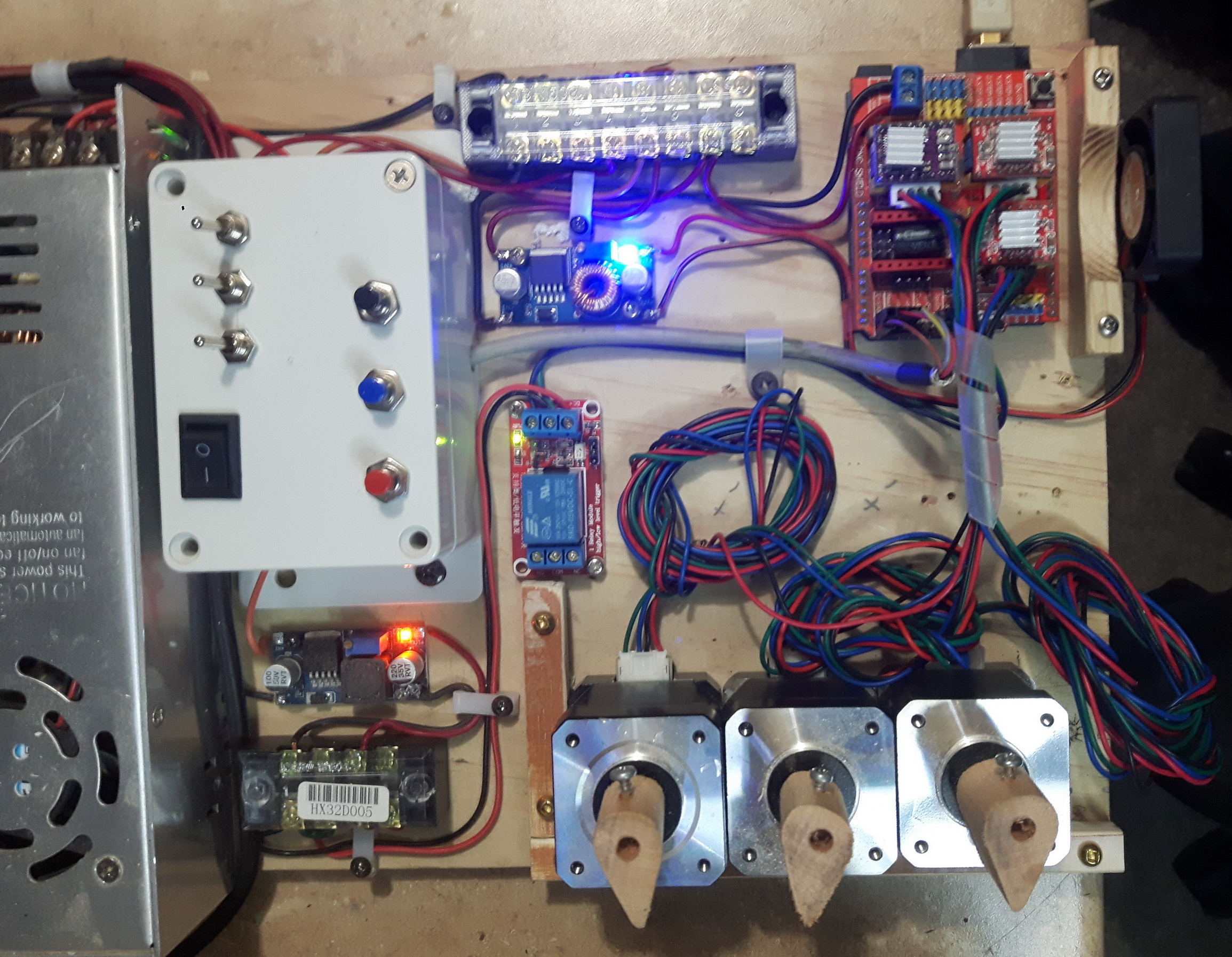
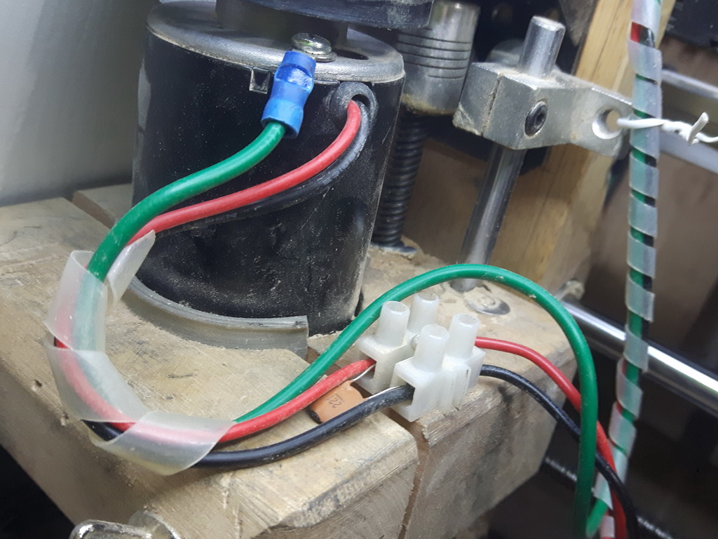
You asked for some extra pics.
One badly shows a ferrite and I used the shielding to run a ground to the speed control case but it also (sort of) shows the heat shrunk end.
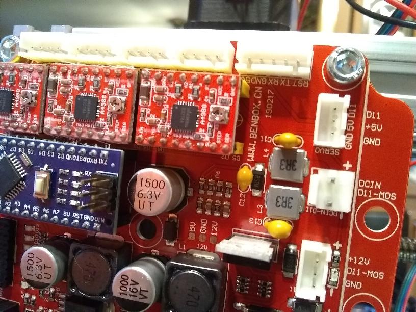
Other is the new CNC test board.
If I suspect a part is dead I can swap it out against a known working one.
Used the spare 24V PSU I had.
The relay (almost centre) is for spindle control but will be adding another for fan control too.
You can see I also mount the heatsinks with the fins in the same direction so the tiny fan (far right) pushes air over easier.
Two chinese voltage droppers also employed. One gives me the 5V i need for the relay and the other gives me the 12V I need for the fan.
You can also see the shielded cable running to the main switch box.
Push buttons for the GRBL functions and the ability to switch the 5, 12, or 24V lines off individually too. (power all kept to one side of the box.
Mounted on a bit of ply so I can move it around or if needed use it as a full backup control system by simply swapping wires over.
Bob.
I like the idea of a test board. Easier to figure out what might be wrong and you know you have the part.
I'll be putting one of those together after I get my head wrapped around what I have coming now.
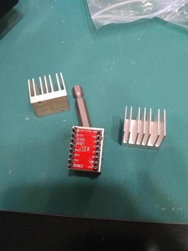
The machine I ordered has the control board mounted vertically. I think you mentioned adding heatsinks to the stepper modules as has everything I've read about them. And I see them in your pics.
Being vertical, is it best to use thermal paste? Or go with a glue or tape? My brain says glue or tape. But other than being somewhat permanent, I really don't know what other cons may be lurking for a noob such as myself.
I guess the only reason I would ever want to remove them would be if a module died. Then it wouldn't matter at all if I damaged the module removing the heatsink.
Did I just talk myself through that?
To use paste you would need retaining clips and there is no provision on the boards I have seen for that.
The glue on tape can become soft with heat and the heatsinks can be jostled around.
I went with superglue and have not yet had any heatsink failures.
And yes you talked to yourself a lot I heard. ... JK.
Bob.
Final part of my parasitic jigsaw.
Now running total "lights out" with zero issues.
Run the motor case ground cable back to the spindle PSU case where I have my star ground located.
Bob.
ballscrewbob:
I went with superglue and have not yet had any heatsink failures.
Super glued parts can be separated with heat. Although, if one of those modules gets that hot, you have bigger problems. Super glue it is then!
Is the green wire the ground you speak of? Looks like you added that. Grounding that to the power supply really help that much?
Or you can buy a bag of 20 of those heatsinks without the adhesive tape for about $1.00 CDN !
Grounding motor cases is a common enough practice anyway even in industry.
In my case it helped and in your case it is easier to do during the machine build.
getting it to follow my add-on drag chain was fiddly.
A machine FRAME ground is also a useful addition.
You can always include it in the spiral wrap too.
Bob.
Thank you ballscrebob! For clearing up the "Star grounding". I assumed that is what you meant by that. But me and any form of the word "assume" don't tend to get along.
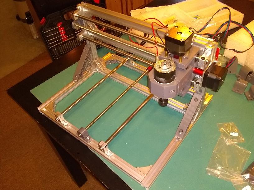
Got my machine today. Couldn't help but do a rough assembly without any add-ons or mods. Wasn't able to get the Y-axis table mounted. The screws are about 2mm too short. So, have to head to the hardware store tomorrow. Aside from that, it went together pretty well. (If someone is thinking about a machine like this and CAN'T assemble something like this without directions, don't purchase a Chinese 3018 CNC. There are no directions for these things).
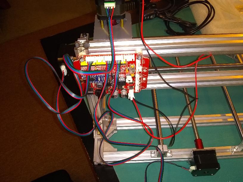
Planning to install limit switches, of course. The board only has sockets for 3 (x,y and z). So, I'll have to double up if I want them on both ends of an axis. The board says "www.benbox.ca" on it. That's really the only markings that might point to more information. Haven't checked it though.
Going to stare at it for a few hours and decide what kind of mounts I need to make for the limit switches. Figure out how to run the wires and secure them. Etc, etc, etc.
Also, I ordered a machine that was shown with and came with the brass 8mm to 6mm (I think) shaft connector for connecting the bit/mill. However, to my amazement, it came with an ER11 already attached to the motor.
I'll have to cut these down just a bit. Dremel to the rescue!
See that stick up MOSFET...See if you can mount a heatsink on it but bigger then the driver board ones.
Probably nothing to worry about but if it were my machine I would feel a little happier.
Not sure if you may have already checked the tracking for the X and Y ?
If not remove the steppers and slide the assembly to the very end of each direction to make sure there are no tight spots. If there is then slacken off two mounts on one bar and let it relax into position while sliding back and forth. Oh and of course check it is still parallel to the frame.
The closer you get those parallel movements the more accurate your corner cuts will be.
Otherwise you will probably cut a slight diamond shape.
Used the digital vernier here for most of that work.
When the table is on you can use that as the ZERO to set the Y rails to run true to the table.
Once it is completely built go around every nut, bolt, screw and double check they are tight.
You look to be doing well there young padawan ![]()
Bob.