I am in the process of making a sound module for my son's car but after several weeks of struggle. anyone who can help. It must be like this when he presses the accelerator (the switch) which secures the buckle when the car is moving. and that would mean reach the arduino for a HIGH signal the motor sound should run and LOW it should switch off / pause
using arduino uno
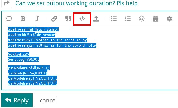
> #include "SoftwareSerial.h"`
> SoftwareSerial mySerial(1, 0);
> # define Start_Byte 0x7E
> # define Version_Byte 0xFF
> # define Command_Length 0x06
> # define End_Byte 0xEF
> # define Acknowledge 0x00 //Returns info with command 0x41 [0x01: info, 0x00: no info]
> # define ACTIVATED LOW
> int buttonNext = 2;
> int buttonPlay = 3;
> int buttonPrevious = 4;
> boolean isPlaying = false;
> void setup () {
>   pinMode(buttonPlay, INPUT);
>   digitalWrite(buttonPlay, HIGH);
>   pinMode(buttonNext, INPUT);
>   digitalWrite(buttonNext, HIGH);
>   pinMode(buttonPrevious, INPUT);
>   digitalWrite(buttonPrevious, HIGH);
>   mySerial.begin (9600);
>   delay(1000);
>   playFirst();
>   isPlaying = true;
> }
> void loop () {
>   if (digitalRead(buttonPlay) == ACTIVATED)
>   {
>     if (isPlaying)
>     {
>       play();
>       isPlaying = false;
>     } else
>     {
>       isPlaying = true;
>       play();
>     }
>   }
>   if (digitalRead(buttonNext) == ACTIVATED)
>   {
>     if (isPlaying)
>     {
>       playNext();
>     }
>   }
>   if (digitalRead(buttonPrevious) == ACTIVATED)
>   {
>     if (isPlaying)
>     {
>       playPrevious();
>     }
>   }
> }
> void playFirst()
> {
>   execute_CMD(0x3F, 0, 0);
>   delay(500);
>   setVolume(27);
>   delay(500);
>   execute_CMD(0x11, 0, 1);
>   delay(500);
> }
>
> void pause()
> {
>   execute_CMD(0x0E, 0, 1);
>   delay(500);
> }
>
> void play()
> {
>   execute_CMD(0x0D, 0, 1);
>   delay(500);
> }
> void playNext()
> {
>   execute_CMD(0x01, 0, 1);
>   delay(500);
> }
> void playPrevious()
> {
>   execute_CMD(0x02, 0, 1);
>   delay(500);
> }
> void setVolume(int volume)
> {
>   execute_CMD(0x06, 0, volume); // Set the volume (0x00~0x30)
>   delay(2000);
> }
> void execute_CMD(byte CMD, byte Par1, byte Par2)
> // Excecute the command and parameters
> {
>   // Calculate the checksum (2 bytes)
>   word checksum = -(Version_Byte + Command_Length + CMD + Acknowledge + Par1 + Par2);
>   // Build the command line
>   byte Command_line[10] = { Start_Byte, Version_Byte, Command_Length, CMD, Acknowledge,
>                             Par1, Par2, highByte(checksum), lowByte(checksum), End_Byte
>                           };
>   //Send the command line to the module
>   for (byte k = 0; k < 10; k++)
>   {
>     mySerial.write( Command_line[k]);
>   }
> }