I want to control the speed of a 12V fan using an Arduino (I'm using components I have at home), but I'm not sure if the circuit diagram I've designed is correct.
Details:
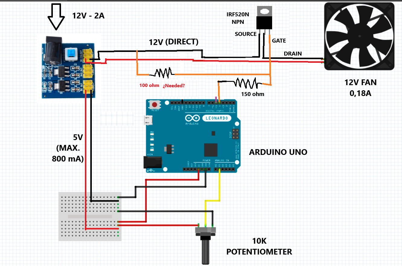
The power source is a 12V – 2A adapter, connected to a small regulator board that outputs 12V (direct) to the fan and 5V to power the Arduino and the potentiometer.
Fan: 12V – 0.18A
Potentiometer: 10K
Questions:
I only hace IRF520N transistor (but I can buy more models).
Do I need a pull-down resistor to ground from the transistor's "Gate"?
Note: I know it's oversized, but in the future, I'm going to add temperature and humidity sensors along with a small screen to control the enclosure of a 3D printer.
With that FET you sure will have a controlled speed, but it won't be by PWM. Lowest RDS(on) spec'd is 10 V
@jim-p got a recommendation, and there are several more FETs to choose from. Try 'logic level MOSFET'
100 Ohms resistor needed? It's way too low - voltage divider calculation: 150/(100+150)*5=3
At 3 V it's doubtful that the FET will even turn on. Lets say you use a 100k resistor instead, that will pass 4.99 V. Is it needed? Its importance is low but nevertheless it makes sure that your fan is off when you start up the circuit.