Diesel Glow Plug Controller Project

Hello All,

Project: Glow Plug Control System for Diesel Engine

Specifics: Temperature based control to determine control circuit timing of glow plug circuit.

Looking for some basic guidance to get the ball rolling on this project. I already have most of the main components, I have written a high level overview of the complete system and expected operations. I also have got code running for the Bosch 0 280 130 026 NPT Temperature Sensor.

I have several inputs that are from the Automotive 12v system that I believe need to be brought down to 5v logic level input signals.

Input signals:

  1. 12v KeyOn power, this will provide power to the unit
  2. 12v Starter signal, this will indicate when in is cranking
  3. 12v Alternator signal, this will indicate engine is running
    3a) VR signal reading from flywheel teeth as already planned to implement with tachometer, Potentially cleaner signal and easier to implement.

Now I know that those 12v signals will need to be conditioned and cleaned to prevent damage to the Arduino. I also know that has been talked about extensively already, but I would like some advice on building a shopping list.

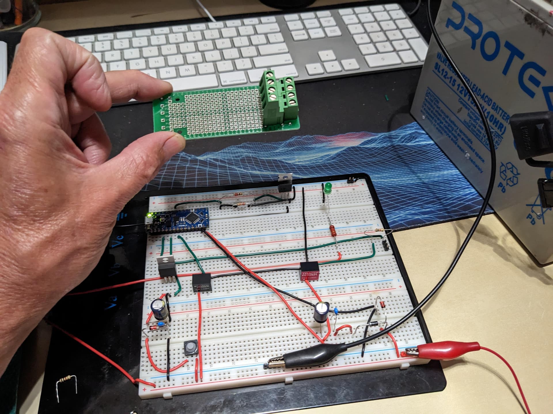
I already have a Traco TSR-1 12v to 5v DC-DC converter I was going to use to send the 5v signal to the Bosch Temp Sensor.

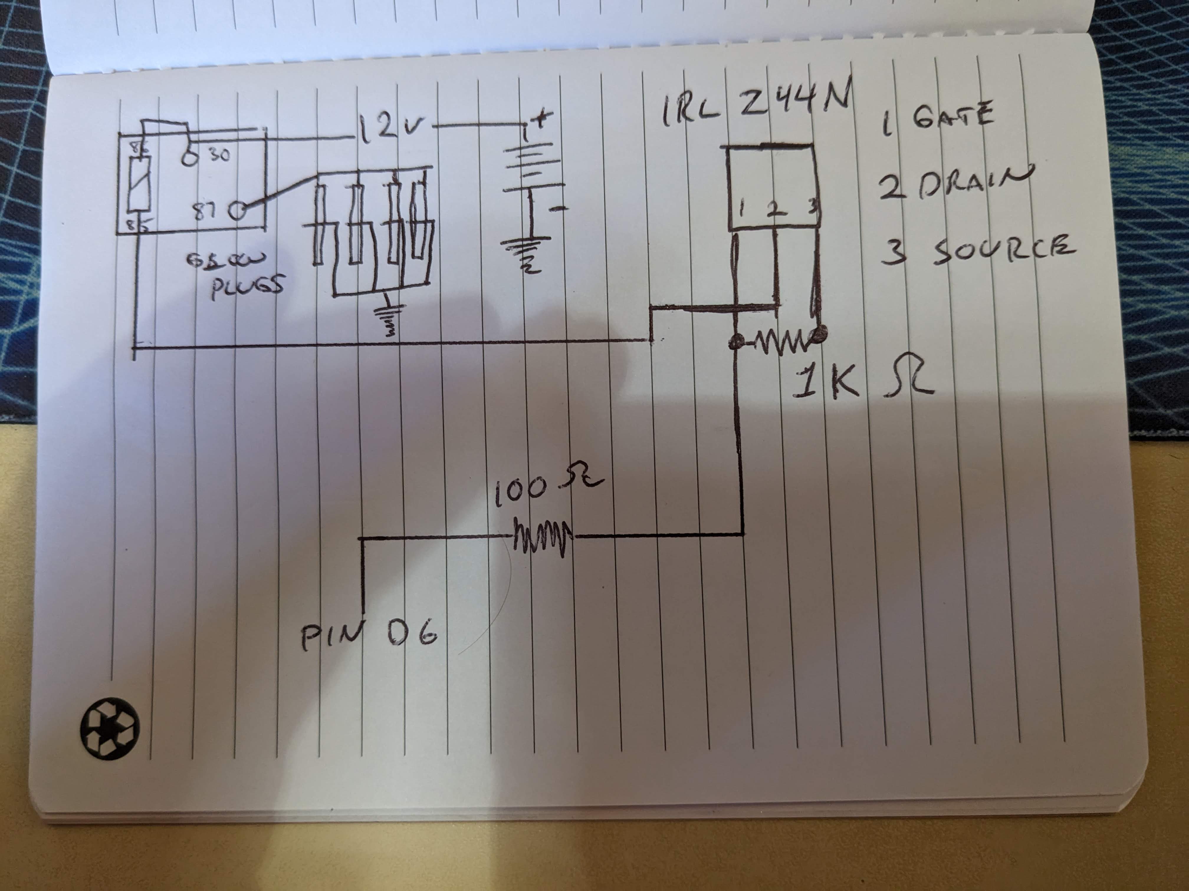
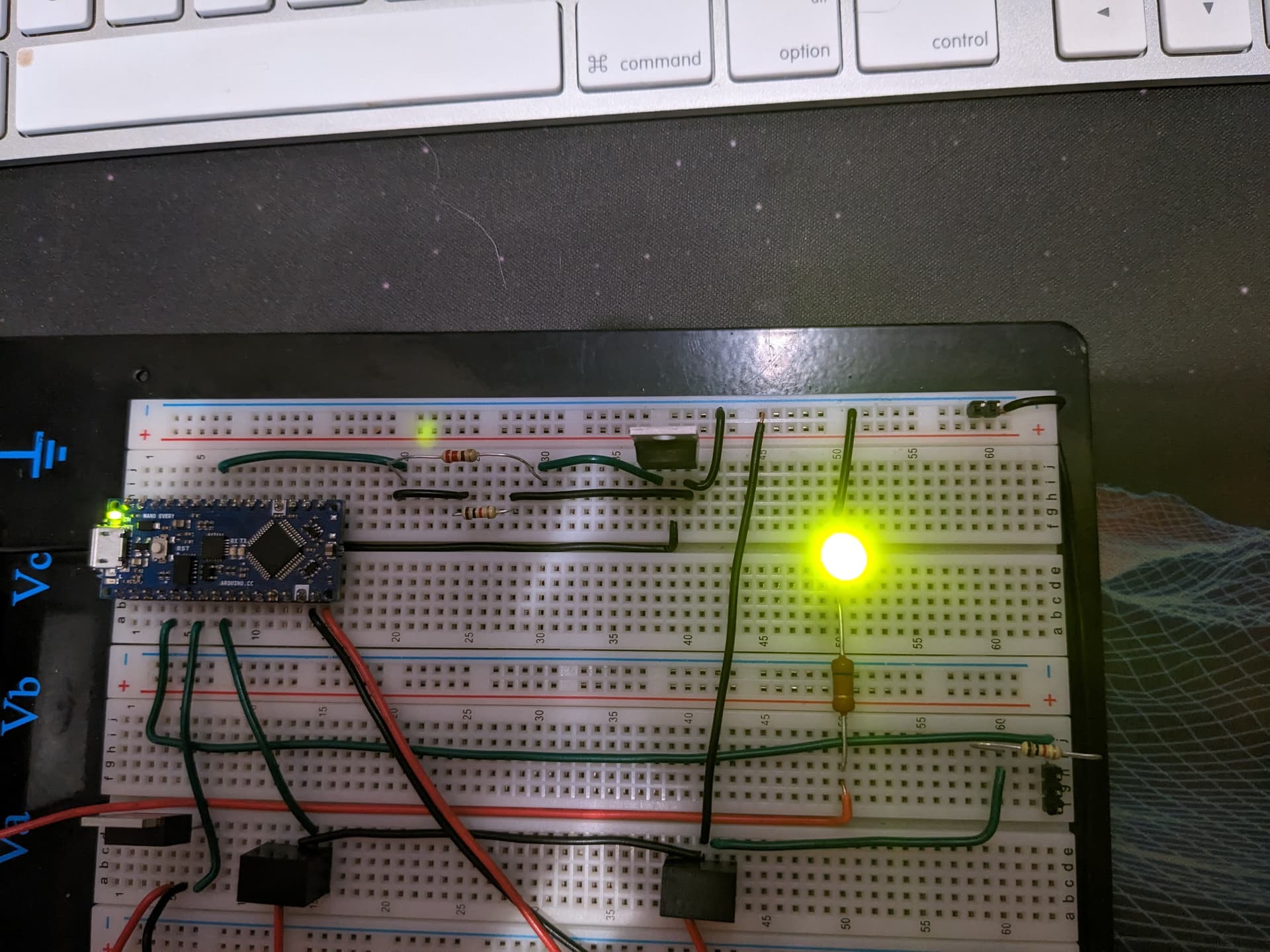
Currently using the Arduino 5v output, 1K resistor and then input that signal on A0 with the second pin going to the Arduino ground. This produces a clean signal that is already been coded and tested and responds to temp changes as expected.

My intention is to use the Arduino 5v output through a N-Channel Mosfet to drive the 12v 75amp relay that will power the 4 glow plugs.

Now on those 12v input signals, I understand I am going to need some 10uF capacitors and a 7805 linear voltage regulator on each input to pull down the 12v to 5v for analog signaling.

In addition for anyone thinking to ask my experience...I have been working in Automotive for 30 years, I have a excellent understanding of electrical, but only a basic to intermediate knowledge of electronics. In regards to the programming aspect I have only general understanding from a couple basic programming course but luckily I have a talented friend who is helping me with the coding side of things, I also have you guys (and gals) :wink:

I am including an a couple attachments for your review so you can get the big picture. Ultimately we are re-creating a factory Glow Plug controller that we do not have and is not readily available as the engine was never sold in the US.

I have all the hardware to implement the actual circuit such as the glow plugs, temp sensor, relay, arduino, multimeter, test battery for 12v power, etc. I also have some zener diodes, 330ohm, 1k ohm and 10k ohm resistors.

The controller_overview is my written work and the 4M40_glowplug ops is pulled from the factory service manual.

My goal of this post is to build a list of electronic items I need to order to be able to successfully complete the project. In addition, any overall guidance on the project. I will search threads for things such as how to implement the 7805, how to wire up the N Channel Mosfet, etc.. as I am sure those topics have been covered before me.

And Yes, I have a copy of the ST AN2689 :wink:

Mitsu_4M40_GlowPlug_Ops.pdf (157.4 KB)
Controller_Overview.pdf (29.8 KB)
T

Hi,
Looks like a great project.
You could also check oil pressure for engine running.

Having been asked at times to repair these devices and with the cost of replacement, making your own is certainly viable.
Not a lot of I/O and some basic logic.

Thanks for the concise info on what you have and what you are wanting to achieve. :+1:

Tom.. :grinning: :+1: :coffee: :australia:

I would suggest using opto-isloators for all circuits.
I certainly hope you are not considering a "universal design" for any automotive Diesel engine. The 1981 Chevrolet V-8 Diesel used 6 volt glow plugs operated at 12 volts with a 30 second timer in the circuit. My MB 300SD 5-cylinder Diesel used a 12 volt glow plug for each cylinder. Usually one or 2 were burned out. My 1997 Dodge Diesel pickup uses a glowing screen in the intake to heat the air.
Glow plugs are a pain in you know where. The Dodge has never had a problem. I suspect my VW Diesel also has a heat screen in the intake as it has never had a problem.

1 Like

Hello Paul,
The application I am building this unit for is a 4 cylinder diesel with 1x 12v glow stick per cylinder. This system operates primarily based on temperature sensor input that determines energize time for the circuit. All of this is explained very clearly in the documentation (pdf) I provided for review.

Glow plugs should not be a pain in the arse if they are implemented properly. The 81 Chevrolet diesel was a great example of a poorly engineered setup. That is a perfect example of a great retrofit for the unit I am producing as the unit I am producing is only the control unit for the relay(s), it doesn't matter if your using a single heater screen such as the Dodge Cummins or a V8 running 2 relays controlling 4 glow sticks each or 8 relays controlling 1 glow stick each.

The control unit just determines the time to live for the output to the control relay(s), what ever that may control, ultimately is of no concern to the control unit. So yes, ultimately this could be a 'universal design' for the aftermarket diesel market. But that is not my intention, my only concern is the find a solution to the engine I am building which is the Mitsubishi 1997 4M40 Turbo Diesel.

Ok so I realized I have a couple N Channel Mosfets I had ordered last year for a different project and can instead use them as the 12v relay driver from the 5v Arduino output signal so that is good. I also have the single Traco TSR-1 to provide a clean 5v signal to the bosch temp sensor from the 12v vehicle source.

So on my digikey order list so far I have the following items:

STMicroelectronics 1N5817 DIODE SCHOTTKY 20V 1A (Provide reverse polarity protection on 12v inputs)
Panasonic EEU-FC1C221 CAP ALUM 220UF 20% 16V RADIAL (Provide smooth 12v signal in the event battery drops voltage during cranking, supress voltage spikes.)
Vishay CAP CER 10000PF 440VAC Y5V RAD (.01uF ceramic disk cap to filter line noise in 12v inputs)
Texas Instruments LM7805 IC REGULATOR LINEAR 5V 1A TO220-3 (Pull down 12v starter signal to 5v analog input)

If anyone sees any glaring errors in my materials or has better solutions I would love to hear it. But please, if you do have input, please provide a part number. Just saying 'Use Octo-Couplers' without giving any reference is useless as there are literally tens of thousands of variations on the market.

Also I am not really sure about the disk style capacitors for suppressing line noise, they are automotive rated, but I am not sure I need them, but Its literally only a few dollars so I don't mind. But if anyone has an opinion on them I would appreciate the input. Thanks.

The N Channel Mosfets I have available on hand are DigiKey R6014YNXC7G and a IRLZ44NPBF

Datasheets:

Cool put in a digi-key order for a load of parts to get this project going. Hoping to get it all in the post before the holiday weekend.

I have been working on a 'on' time strategy for the glow plugs. Since we never had the glow plug controller and do not know the original timings I will have to just kinda make up some numbers and adjust as needed once the engine is up and running.

Using 5 data points starting at -20C = 15sec, 0 = 12sec, 20 = 8sec, 60 = 5sec, 70 = 3sec.
I will attempt a exponential equation that will attempt to create a smooth curve that is biased torward the cold side. Then for the after glow I will start with an addition 15sec@ -20 and reduce the after glow time down to zero at 70*C.

Once I have that figured out I can get chatgpt to generate a working code snippet that I can tie into my already working temp sensor code.

Thats all for now.

I figured you guys and gals might want to actually see the engine I am putting this project together for. I build this engine from 2 engines. One was pretty decent from Japan but had shipping damage and water in the cylinders that required new sleeves. The other engine was a horribly thrashed engine from Austraila. It was mostly scrap but we have been able to scavenge a part here and there and the bare block was instrumental in getting an adapter plate made to mate up the Renault 5 speed transaxle :slight_smile:


Nice looking project. Nice shop, also!
One way to calibrate your glow plug timing might be to get one all set up on the bench and ready to power. Coat the glow plug tip with Diesel oil. Power the glow plug and time the power on till the oil vaporizes. That will be more closely represent the action of the glow plug in it's chamber in the motor.

So today's progress was to get the relay control circuit working with the IRL Z44N n-mosfet. I got it wired up and working with just basic digitalWrite on off code. Also threw in a yellow led to represent the glow plug hooked to the working side of the relay. I will start drawing up a circuit diagram tomorrow.

All my parts shipped from DIgiKey today so hopefully can make some solid progress over the weekend.

Hi,
Great stuff, a section at a time, will keep the bugs out.

Tom.... :grinning: :+1: :coffee: :australia:

Oki Doki, I am back after a 70 post thread getting the Arduino power filtering circuit squared away. That was kinda rough going, but I did get alot of good help and I learned a few things along the way so its all good.

So with that circuit finalized, I can turn my attention to the rest. In the above picture I have the N-Mosfet for the relay control and while its working, I am just using some basic resistors for protection but I believe it probably needs some caps and a diode at a minimum since it is literally the workhorse of the operation.

I will be using a LM7805 for the starter input signaling to the Arduino, I will group it up with a some caps and a diode for protection, this circuit should only be operational for up to 30 seconds at a time so a small heatsink should be sufficient.

For the 5v output to the Bosch Temp Sensor I will be using a Traco Power TSR1-2450 DC DC converter. This unit will give a stable and clean 5v signal to the sensor and takes that load off the Arduino's 5v output. I like these as they have capacitors, line filtering, short circuit protection all built into one compact unit.

I will also use same TSR1-2450 on the alternator input signal, this tells the control unit (Arduino) that the engine is running. Again, I like the fact these little units are all in one self contained converters and don't require any heat sinking. This is important since the alternator and sensor will be in operation as long as the vehicle is running which could be hours at a time. Whereas the starter input and glow plug relay output are only operating for seconds at a time so N-Mosfets are a good fit and will only require minimal heatsinking.

I got another order from Digikey showing up tomorrow for another weekend of fun testing. I do need to get some smaller caps as all I have are 220uF and I need something more along the line of 22uF for use with these Mosfets.

My friend is supposed to come over tomorrow and start getting some more of the software requirements in order. He already wrote the temp sensor code that is working on point, now we just need to start getting the glow plug timings and trigger events written in.

After that its moving everything on to perf board and hopefully start testing it on the engine. Although we did suffer a setback on that front. Since this is conversion, the only starter that will fit in the given location is a 1.4Kw and the engine requires 2.6Kw, so we are looking at engineering a gear drive setup to be able to mount the starter motor outboard to clear the injection pump.
Custom automotive on one off projects is always fraught with unexpected twists and turns, and usually all headache inducing, but that is a story for another day.

Cheers!

Might be easier to engineer a compression release system for the engine.

Oki Doki,

Getting the starter input circuit put together. This one is fairly simple but at the same time I do want to exercise caution as the starter solenoid is kicking a 2.6Kw starter hitting engine with 21:1 compression ratio, its a lot of load!

For now we will pretend that the built in relay and solenoid has some circuitry inside that prevents huge load dumps and spikes when the solenoid field collapses. I will be pulling the start signal from inside the vehicle at the ignition switch or very close to it before it goes out to the starter relay.

Now the purpose of this circuit is to send a signal to the arduino to trigger the glow plug relay so that the glow plugs are energized during engine cranking to ensure engine starting performance.

I am using a Texas Instruments LM7805, Datasheet , as per the datasheet I installed a capacitor on the input side. A cap on the output side is optional and not sure I need it for a 5v input to Arduino.

Now the datasheet claims:

The LM340 and LM7805 Family monolithic 3-terminal
positive voltage regulators employ internal current limiting, thermal shutdown and safe-area
compensation, making them essentially indestructible

I am however concerned about above mentioned nasties that might be on the starter relay circuit during cranking. I have decided to use a 20v Zener diode and the same caps I used on the voltage supply filter I created for the Arduino's Vin. I do have a TVS diode that I might I could put in place of the Zener, I will cross that bridge at final design review.

Alright on to some pictures, in the bread board shot I am using a simple push button to simulate the starter signal and installed a LED as a sanity device before plugging into an analog pin on the ardy. Check out the fancy 100 ohm red fire proof high temp AEC-Q200 qualified resistor on the led, thats some fancy $0.40 resistors there :grin:

Updated schematic and layout pic.

Alright well I got all the wiring done, now its time for the hard part, the coding how to make all this work.

I would like some feed back on the relay control mosfet IRL Z44N. Its controlling the ground side of the relay trigger coil. There doesn't appear to be any protections, or diodes in place. I have it wired up with a 1k resister between the gate and source, without it the relay just stays on. I have a 100 ohm resistor on the trigger line from the arduino but other then dropping voltage its not really doing anything.

I tried putting a capacitor on it but that stopped its operation. Anyways I am open to suggestions.

I got 2 Traco Power DC DC step down converters on the 5v feed for the temp sensor, that is a sensitive circuit and did not want to have to scab off the Arduino 5v output. This converter is power off the filtered 12v that is feeding the Arduino Vin Pin15.

The second converter is on the Alternator high signal that will signal the Arduino that the engine has started and is running. This will trigger the 'after glow' on the glow plugs. I went with these converters as they claim to need absolutly no additional components with a very impressive 5,350,000 MBTF rating.

Anyways here is the IRL Z44N circuit for controlling the relay, I just feel like its vulnerable to coil feedback and also the relay is in the engine bay where wires can get rubbed raw and short out, so I would really feel better if I could get some better protection.

IRL Z44N Datasheet


Here is the complete picture, this is all the circuits, except an LED signal out to the dashboard. The LED you see there on the project board is to simulate the glow plugs.

Hi,
This is better, you will then get full digital HIGH voltage on the gate.
10K is sufficient to pull the gate to gnd if left open circuit.

Tom.. :smiley: :+1: :coffee: :australia:

Alright, that works, I used a 1k initially but have installed a 21k as that is all I have. Works just fine, matter of fact the relay coil has a much more pronounced 'click' to it.

Do you think I need any kind of diode in this circuit? Maybe instead of the 100 ohm on the gate circuit I could use a schottky diode to prevent any kind of reverse voltage or surge from the coil inductance when gate goes low? I am over thinking it?

Now for my next hat trick.......

Get all of that stuff onto this protoboard, which I am going to epoxy set into a housing. At least thats the thinking anyways.

Have you looked at some eval boards from ST that does this sort of thing?

https://www.st.com/en/evaluation-tools/ev-vnq9080aj.html#overview

Specifically built for automotive resistive, inductive and capacitive loads

I had not looked at those boards until now, thanks for that link. The device referenced appears to be a pre-made power solution so that you can plug in your own microcontroller and inputs/outputs.

Kinda like jail device that keeps all the electronic nasties at bay and allows one to just get on with the task of building their project.

At least this is the way I interpreted it? It was immediately clear to me and that is the impression I got from it.

Anyone's feedback on how I might incorporate something like this into my project, I would be all ears.

Thanks,

Hello Tom, (or anyone else who feels the desire to chip in)

I am in the final stages of circuit designs and I have updated the IRL Z44N Relay Driver Circuit.

I made the change to the gate pull down, I found in many other successful automotive circuits that they all used a 100k pull down resistor on all transistors and these units are installed in literally millions of cars, so I just copied that specification.

I added a diode on the gate driver circuit. I see no reason to reduce voltage to the gate via a resistor but I was thinking that if something where to go awry in the engine bay and some how we got a high voltage or current surge through the transistor I would want to try to protect the gate drive pin.

Also since the relay coil acts as an inductor every time it switches off and collapses its field, should I be concerned about adding in a fly-back/freewheel diode into the drain circuit anywhere?

Speaking of drain circuit, I have added in 2 LED grounds into the drain circuit, one will be a small 3mm led on the unit case as a diagnostic if needed and the other lead will go up the instrument cluster to drive a large 8mm in dash LED for the operator to have visual indication of when the relay is in operation. Lets assume the leds will have the appropriate resistor on the 12v anode side.

Not sure if I need a diode on that on that feeder, can't hurt I suppose, but less components makes for a less cluttered board.

And last musing, do I want or need a capacitor between the drain and source pins?
I have .15uF ceramic and 22uF electro's rated at 25v.

I am going to ditch the 220uf@16v caps throughout the entire design. But that is not an issue in this circuit.

Thanks again,