I am trying to make a circuit which reads HIGH when I push the push button. I have tried solution on the net but they are not working either
Post your best effort sketch and a schematic or very precise description of your circuit
You will have to provide a wiring diagram (photo of pen/paper drawing is fine) as well as the code of your attempts.
Be aware that the preferred way is to use a button to ground and use pinMode(yourPin, INPUT_PULLUP). You will have to reverse the logic in the code.
Hi, @vidit_sinha
Can you please post a copy of your circuit, a picture of a hand drawn circuit in jpg, png?
Hand drawn and photographed is perfectly acceptable.
Please include ALL hardware, power supplies, component names and pin labels.
Is this a school/college/university project?
Tom... ![]()
![]()
![]()
![]()
For the wiring, you can look at @LarryD's schematic
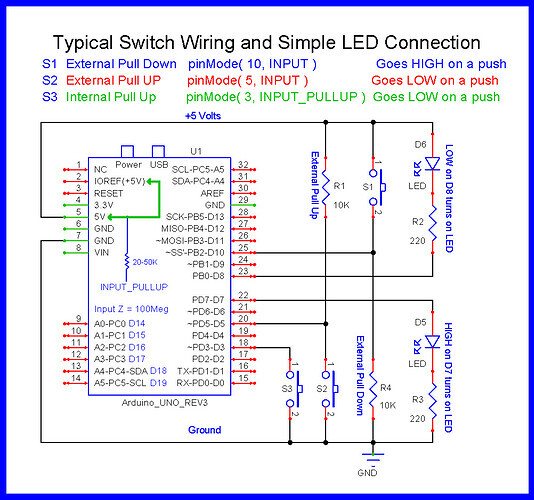
The way switches S2 and S3 are wired is the preferred way; S3 will save you a resistor.
I am using pinMode(yourPin,INPUT)? Is it wrong?
It is not wrong as long as your circuit and program logic match it
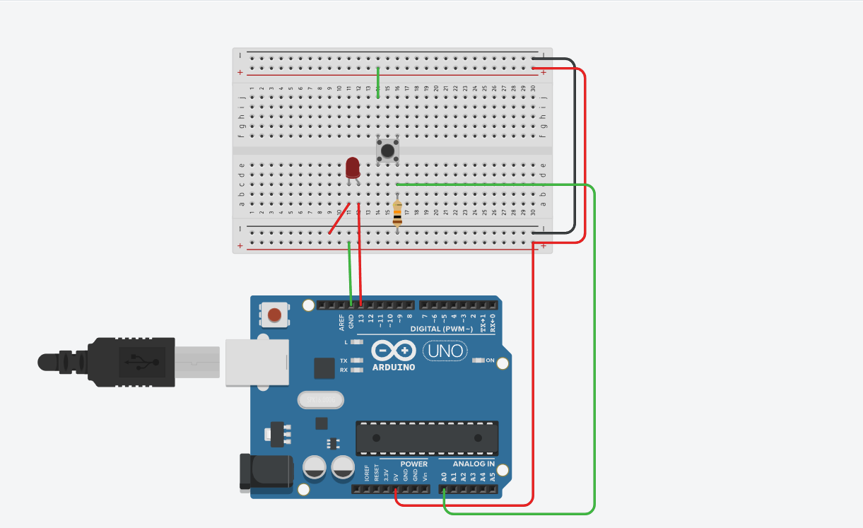
As an aside, your circuit does not show a current limiting resistor in series with the LED. Have you got one in place ?
When I am printing the digitalRead on Serial monitor, it only prints 1 and does not reflect the push button input
Post the sketch showing how you are printing the state of the input

That will be a problem due to this:
The lack of a resistor means that pin 13 will start to source theoretically unlimited power; generally an ATMega controller will lock up under those conditions and potentially burn out.
Remove the LED and the code related to it and see if it works.
Also:
Why?
Why not the regular approach of using INPUT_PULLUP and connecting the switch between the input pin and GND (no additional resistor)?
Even when I remove the LED and pin 13, it only prints 1 on serial monitor.
This is a small sample circuit I made because I was struggling with a problem in my circuit of running my motor with L293D where it runs forward if I push button 1 and backward if I push button 2.
int ford = 8;
int back = 12;
int fordI = A0;
int backI = A1;
void setup()
{
  pinMode(ford, OUTPUT);
  pinMode(back,OUTPUT);
  pinMode(fordI,INPUT);
  pinMode(backI,INPUT);
  Serial.begin(9600);
}

void loop()
{
  //Serial.println(digitalRead(fordI));
  if (digitalRead(fordI)==1)
  {
 	 digitalWrite(ford,HIGH);
  	 digitalWrite(back,LOW);
  }
    if (digitalRead(backI)==1)
  {
 	 digitalWrite(ford,LOW);
  	 digitalWrite(back,HIGH);
  }
  //Serial.println(digitalRead(fordI));
  //Serial.println(digitalRead(backI));
  delay(100);
}

Stick with your simple test sketch until it works properly. Leave the LED out of the circuit for now and also remove the pushbutton. Use a jumper wire to connect the junction of the resistor and the connection to the pin to GND. Does the pin state change from 1 to 0 ?
Is the breadboard that you are using exactly like the one in the diagram or is it perhaps a longer one with gaps in the centre of the long power rails along each side ?

Disconnect the Uno from the breadboard and use a jumper to take pin A0 to either 5V or GND. What is printed ?
Try different pins
In your drawing in post #15 you have shorted Vcc and GND
It prints 1
What about other pins ?
A0 connected With pins other than GND, it prints 1