I consider myself a hobbiest, so my knowledge here is limited. At my dayjob I have these powersupplies that have an serial output for their RCU controllers through a single wire connected to an external socket. I am trying to design a 4 led testing unit so I can do field test on these. My question is where should I start equipment wise to:
1 read the outputs (4 direction controller)
2 convert the outputs to something that could transmit to the LEDs
If it helps there are 2 transmitter in the unit is a CC2510-F8 and a CC2543. Any resource would help.
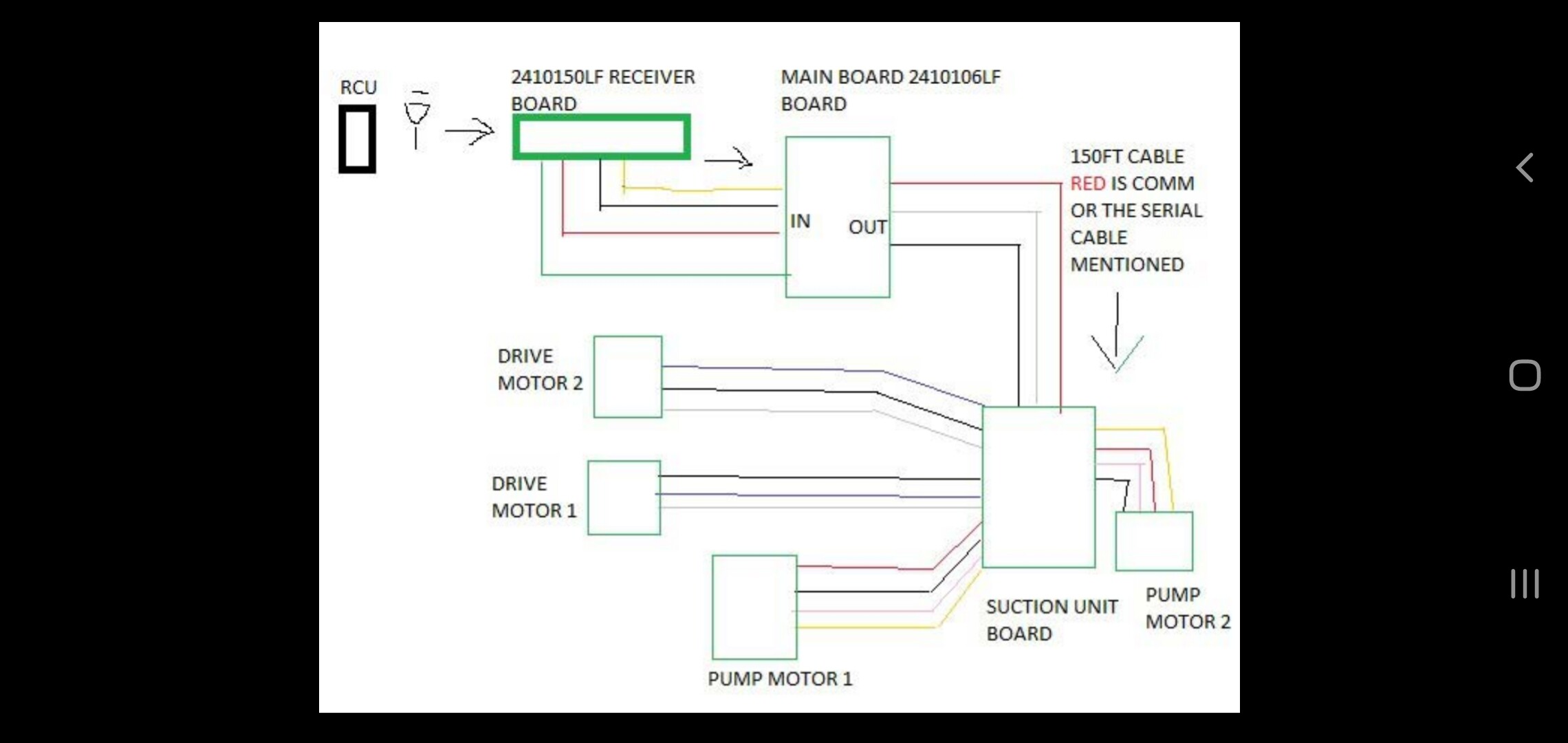
The RCU is transmitting to that board, there is a 4 wire connector on the same board that transmits to another board which carry the signal to the serial wire, the serial wire then carries to the motor unit and based on what is pressed changes the rotation of the motors in the final unit.
@TomGeorge Sorry! Jumped the gun a bit. I hope these post in order. I tried my best to consolidate the pictures. The unit is a vacuum for pools. The full technical data is unfortunately withheld by company policies. The unit functions as follows:
Remote control unit is turned on while vacuum is working. This kills the programmed controls to the motors and allows override with the RCU
Pump motors operate and unit waits for RCU input
Depending on what button of the 4 is pressed unit will move move the motors together or in opposite directions (independent input codes I imagine?)
The main idea is to test the RCU transmitter at the power supply socket, and at the cable connector for the suction unit by using 4 LEDS for the signals.
Power supply board. 4 pin connector on board is for the RCU board. 3 Pin connector is power and the single red wire mentioned that carries the comm to the suction unit