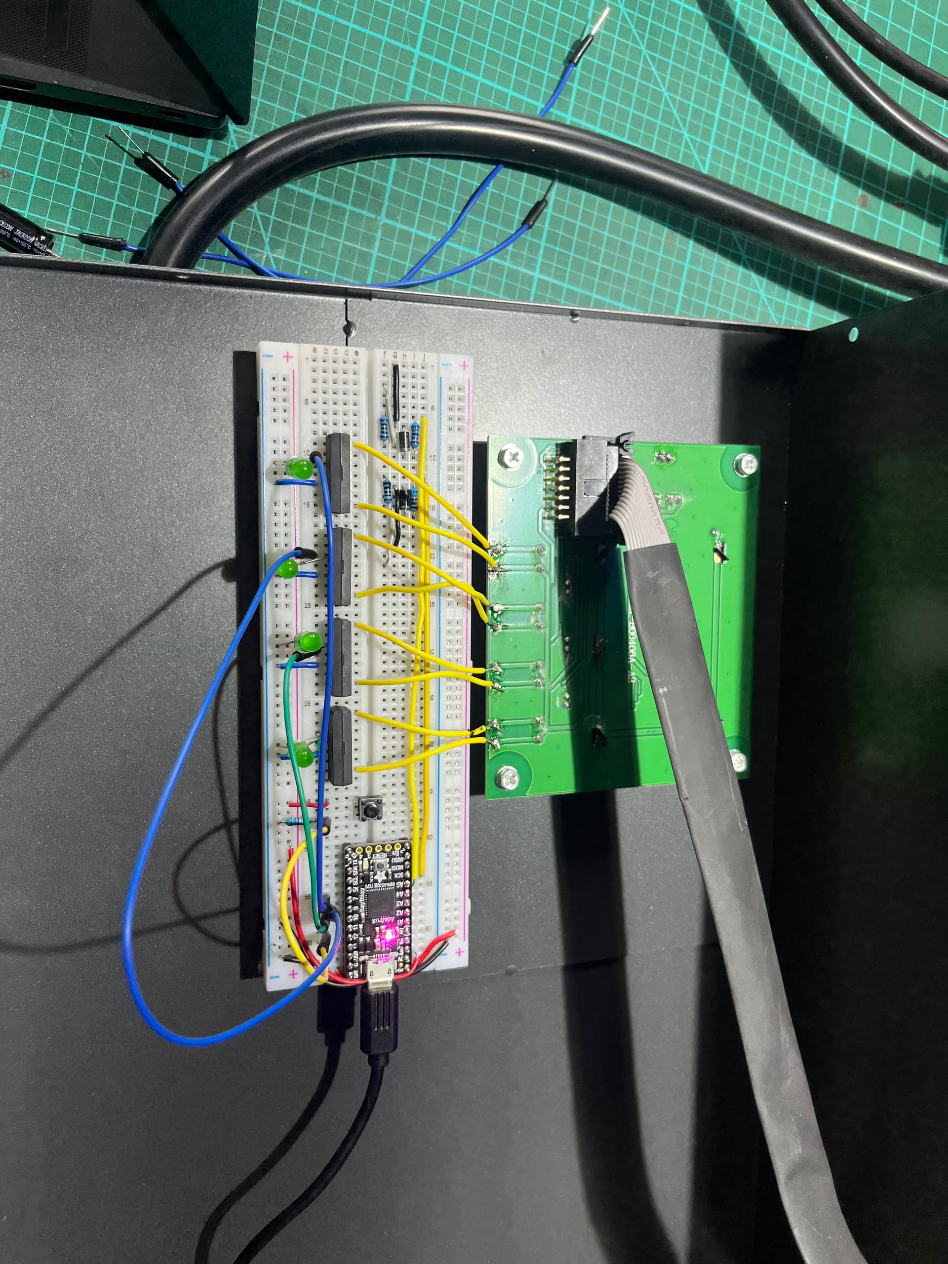
Hey everyone! Full disclosure here, I'm a mechanical engineer so this is outside my range of expertise so I'd really appreciate any help and suggestions you can offer. I'm currently working on a project where I'm using an Adafruit ItsyBitsy M0 to control the charge current on a PowMR 5kw pure sine wave inverter charger combo for a school bus camper conversion I'm working on. The inverter has RS485 for communication but as far as I can tell I can't use it to change the charge current. The next best option I could think of is simply simulating pressing the pushbutton switches on the interface using some NPN transistors. This seemed to work great as long as the actual inverter part of the inverter charger was off. As soon as the inverter kicks on and the AC output goes live, the ItsyBitsy locks up and stops responding (though it still has power). I'm currently powering the ItsyBitsy using a battery so I suspect the noise is somehow making its way back through the gate pin and into the MCU. Measuring the noise using an oscilloscope, I'm getting around 150mv RMS. The next thing I tried was replacing the NPN transistor with a relay but I get the same issue. Is 150mv RMS a lot of noise? Is it common to get coupling across a relay like this? I've attached a photo of my current breadboard setup and how its connected to the inverter interface below for reference.


To add a few more details,
I've tried both regular relays as well as reed relays with the same result.
A schematic would be more useful than those photos.
Here's my code for reference.
const uint8_t buttonPin = 12;
const uint8_t setPin = 11;
const uint8_t upPin = 10;
const uint8_t downPin = 9;
const uint8_t entPin = 7;
bool buttonState;
int setCurrent;

void setup() {
  pinMode(buttonPin, INPUT);
  pinMode(setPin, OUTPUT);
  pinMode(upPin, OUTPUT);
  pinMode(downPin, OUTPUT);
  pinMode(entPin, OUTPUT);
  Serial.begin(9600);

}

void loop() {
  buttonState = digitalRead(buttonPin);

  if (buttonState == HIGH) {
    //Serial.println("Button pressed");
    changeChargeCurrent(20);
  }
}

void set (int set) {
  for (int i = 0; i < set; i++) {
    digitalWrite(setPin, HIGH);
    delay(300);
    digitalWrite(setPin, LOW);
    delay(300);
    Serial.println("set");
  }
}

void up (int up) {
  for (int i = 0; i < up; i++) {
    digitalWrite(upPin, HIGH);
    delay(300);
    digitalWrite(upPin, LOW);
    delay(300);
    Serial.println("up");
  }
}

void down (int down) {
  for (int i = 0; i < down; i++) {
    digitalWrite(downPin, HIGH);
    delay(300);
    digitalWrite(downPin, LOW);
    delay(300);
    Serial.println("down");

  }
}

void ent (int ent) {
  for (int i = 0; i < ent; i++) {
    digitalWrite(entPin, HIGH);
    delay(300);
    digitalWrite(entPin   , LOW);
    delay(300);
    Serial.println("ent");

  }
}

void changeChargeCurrent(int current) {
  Serial.println("change current");

  set (7);
  //up (7);
  //ent (1);

}

There are few relays that can be directly driven with an Arduino output. The relay coil needs a transistor driver.
What are the specifications of the reed relay. Like the pull in current and voltage?
Most solid state relays are AC output only. Are you sure that yours was a DC output SSR?

Is there really no current limit resistor for that LED? Should be at least 220 Ohms up to 1K or so.

The more accepted way to wire a momentary switch is to wire one side to ground and the other side to a digital input set to INPUT_PULLUP. The cap will help to debounce the switch and bypass environmental noise to ground.

The schematic comments are valid, though may be beside the point. Often in these EMI (electromagnetic interference) scenarios the physicality is at least as important as the schematic. Particularly since changing from a NPN to a relay didn't make a difference. Incidentally, a NPN and relay is a big change - the NPN references your circuit to the inverter while the relay allows them to float isolated.
To answer your questions, no 150mV isn't typically a lot of noise in a digital circuit and no, you don't usually see a lot of coupling across a relay. But, noise is very hard to measure reliably, and coupling has many forms. Inverters are some of the worst emitters of EMI, with very big, very fast transients. The EMI is both conducted and radiated. So even if you have a relay with zero capacitive coupling, you can still pick up plenty of EMI through the air.
You've done a really nice job of the circuit, particularly the fact the load side of the wiring mostly crosses your own circuit at right angles in a short, direct path. But the breadboard itself doesn't do you any favours - all the internal tracks make controlling coupling difficult.
So I think the first thing I'd do is try to figure out if the major effect is conductive or radiative - if you remove the relays completely and leave everything else the same, what happens?
In any case, if you want a sensitive bit of electronics like an Itsy to work near an inverter, what you want to try to do is shield it. A PCB provides a lot of this for free, so you have to work a bit harder on a breadboard. A shield is a continuous conductive path that encloses the entire circuit, battery included. So maybe think about putting it all in a metal box (or a plastic box lined with copper foil or something), and then bundling the 8 wires to the button panel and poking them out a single orifice in the box.
Then, if it is indeed a conductive EMI issue, you need to isolate your circuit from those 8 wires. Instead of chasing your tail looking for a beefier relay, use ferrites on those 8 wires. Either the cylindrical ones that go around the wires (make sure they go around a pair or even all 8), or series ferrite beads that go in line with the wires. That will impede the high frequency content (which in this case is all bad and you want nothing to do with it) from ever getting to your circuit, and will help a lot. Even adding some series resistance may help.
By the way, the typical element you would use in this scenario is not a NPN or a relay, but an optocoupler. They are much easier to drive from a microcontroller like the Itsy, but still give you that galvanic isolation like a relay does. But either is fine and I don't think it is at the heart of the matter here.
Thanks for all the great suggestions. To answer your questions:
-
I specifically chose this reed relay since it only draws 6mA at 3v. It's a reed relay so it's not solid state
-
The LED is being driven by 3.3v which I don't think requires a current limiting resistor. Good point though and I'll throw in a 220 ohm to be safe
-
Ah good to know. I forgot about the internal pullups. I'm not picking up any switch bouncing issues at the moment but I'll also toss that cap in to be safe.
Wow this is incredibly helpful and I really appreciate the advice. I'll go ahead and run some tests to see if its conductive or radiative tomorrow morning. I'll also get my hands on some ferrite beads and try those out. I also thought of optocouplers right after I placed the Digikey order for the relays but I'll go ahead and buy some of those to play around with them when I order the ferrite beads. Stay tuned for updates.
I was able to solve it! So it seems like the issue was related to some EMI stuff and the long data wires that were being used to drive the relays were picking some of that up and causing the MCU to tweak. I also believe the pushbutton switch I was using to trigger everything was picking up some interference from being too close to the yellow inverter side switch wires so moving that also helped. The lesson: inverters are noisy and keep sensitive components well separated on a breadboard and avoid long wires even if they are perpendicular to the things they cross.