Hi, I've been trying to figure out my interference problem with a new batch counter I made for my company. I'm using a normally closed relay that is switched open by an arduino, and it works perfectly when no 115v is being passed through the relay. But when I turn on the power so the clutch will turn on/off, the arduino will reset/stop working about every 10-20 counts. I looked on here at problems similar to mine, but the solutions are all over the place and I'm not too well versed with capacitors/diodes/resistors to be able to create them myself. My schematic is below, but will you help me make and integrate a snubber curcuit/ decoupling capacitor? Or tell me if the RC Absorption Snubber Circuit I found on Amazon will do the job and how to integrate it into my electronics?
Good start with the schematic. This sounds like EMI (Electromagnetic interference), conducted and or radiated. I cannot say that is the problem but conversely I cannot say it is not the problem without more information. Most MOS logic is fast and definitely edge sensitive. Keeping your leads (they are antennas) connected to the processor less then 10"/25cm which is is about 750 MHz without accounting for reflections etc is very important. Receivers follow the same as transmitters, the bigger the antenna the greater the gain the further it will go the more it will receive. Keep It Short & Simple. Be sure the power and logic lines are not parallel to each other. A possible simple fix use a zero crossing Solid State relay. Can you post a picture of how it is set up?
You may also be using one of those toy blue relay modules that are not upto the job - you need a proper industrial relay and keep the 115v wires well away from the rest of the circuit .
Need a proper circuit diagram and a photo of your circuit .
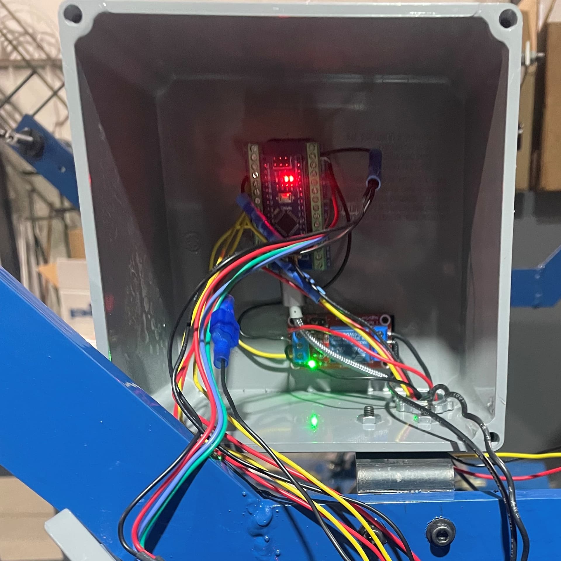
Yikes, my wires are pretty long and the relay is very close. This is a prototype, so I wanted to make everything easy to look at and get to. Here's a picture.
Also, I didn't even think of solid state as an option as when I looked up the relays originally, I only saw the blue "toy" relays. Will solid-state eliminate my problem completely? I can also move the relay to another box that houses the power/electronics for the rest of the machine to give some distance between the relay and arduino. The solid state relays i found are pictured below, which should i use?
Also the other electronics box for reference It's mostly power, but does have a clearcore controller that operates at 20v inside:
Yeah, i didnt know there were other options then the blue ones since they were the only ones that showed up when I originally ordered relays. But will exchanging it for one of the solid state ones I found (and pictured in another reply) fix the problem? or should I move it to the box further away as well (seen in the other reply)?
Your layout needs tidying .
Look at a length on DIN rail across the front of the box with power connections on the left and Arduino connections on the right .
You can get plastic cable trunking to run the wires around the cabinet keeping any hi and lo voltage wires Separate .
The box should be earthed and wires exit through grommets .
Mount the relay close to the mains terminals close to the terminal strip .
A neat layout will solve a lot of issues , make maintenance easier and improve reliability and even safety .
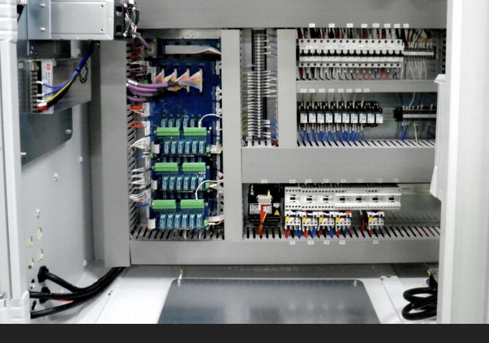
Although more complex , this picture is the professional look to which you should aim :
In addition to what everyone else said:
Circuits work because current can circulate, which at the simplest level means there's 2 wires in every circuit, one to take the current to the load, another to take it back to the supply. Any circuit can be reduced to multiple instances of this basic design. To minimise transmission of noise from noisy circuits and pickup by noise sensitive circuits then the 2 wires should be run together, as they are in a cable. Having them separate from each other makes them into loop antennas and much more susceptible to noise.
A very cheap, easy and "non-invasive" solution is to isolate your electronics from the higher voltages and currents.
In your case it would be to isolate the signals coming out of your board from the signals driving your relays, and they have a name: optocuplers.
They are easily available, cheap and most important, you don't have to modify your circuit at all... if it's already working fine but for the load issue.
You just put the device in the lines you want to be isolated, the basic principle is that your board will not turn on an inductive load (the electromagnet in the relay), but a led inside a plastic casing. On the other side of the plastic casing a light detecting device will receive the signal and give out the activation signal.
You dont event have to know anything else, as they are sold as breakboards, just cut the wires, screw or (solder) the thing in place, connect the powering pins to your power source, as the signal detection part of the device will now have enough juice to send the activation signal. Done!
Take care that they come for differente voltages, in the range 3v3-5V, 12V and 24V being the most usual.
Oh, and when talking about isolation: powering the LCD, the relay and any other device FROM the Arduino board will make electronic interferences a nightmare, get an isolated DC power source, like the ones from Hi-link, because your are giving a highway back for any of the EMI everybody else mentioned here!
This octocoupler sounds magical! I've been looking around and found some, but they don't really say what the output can handle, only the input at 3-5,12,24. Will it be able to handle the 115v ac input from the outlet? One of them says it can handle 24v dc output, but I don't know if that helps much when I'm using ac.
Hi @rouset,
The ones I always used were not meant to work with high currents or voltages, but for isolating the signals that wil drive those voltages and currents, being inductive elements the main usual problem. In your case the coils of the electromagnet that drive the clutch release relay. And those coils come in various standard voltages, but none need high currents!
As I recall, even some of those "toy blue" 5V relays you mentioned come with an optocupler for the activating signal, but not all!!
But once again, try to throw the high voltages, the AC signals and all inductances as far as possible from your electronic "brain", in the case of the relay is as easy as changing the relay to a 12 or 24 DC driver model, or just change the coil, as most industrial relays give you the chance of changing the coil as needed.
For more information about optocuplers you may want to take a look at documentation explaining them at https://www.vishay.com/docs/48034/edn0715.pdf
I did end up trying a snubber, hooked up in parallel to the load. But it doesn't seem to do anything, so I'm wondering if the power is too large for it to change anything or if i hooked it up wrong. The data sheet says it has 0.62A in-rush current, and 0.33A holding current. I'm using the 115v AC version. The snubber I tried was the one from amazon shown in the original post.