In both cases, the diodes are designed to protect the transistors, which are driving inductive loads. They try ensure that, when the loads are turned off, the transistors are not subjected to more than one diode-drop (Vf) of reverse polarity. But don't succeed.
BTW, think you'll find that Darlington pair (TIP120) in the upper schematic is upside-down.
johndg:
In both cases, the diodes are there to protect the transistors, which are driving inductive loads. They ensure that, when the loads are turned off, the transistors are not subjected to more than one diode-drop (Vf) of reverse polarity.
thank you, but I still do not understand why the one diode cathode is connected to the collector while the other diagram the anode is connected to the collector.
The TIP120 in the first diagram is drawn wrong.
Emitter must connect to ground, collector to the solenoid.
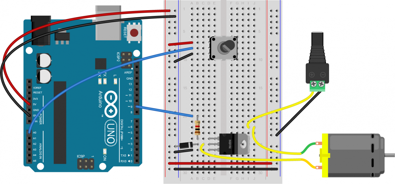
Breadboard layout seems ok though.
Switches are safer when connected between pin and ground, with internal pull up (no resistor).
So pin is normally HIGH, and LOW when button is pushed.
The diode in the third diagram does nothing useful across the transistor.
A kickback diode should limit collector voltage, and can only do so if the anode is connected to the collector and cathode to the supply (so across the solenoid).
Leo..
Wawa:
The TIP120 in the first diagram is drawn wrong.
Emitter must connect to ground, collector to the solenoid.
Breadboard layout seems ok though.
Switches are safer when connected between pin and ground, with internal pull up (no resistor).
So pin is normally HIGH, and LOW when button is pushed.
The diode in the third diagram does nothing useful across the transistor.
A kickback diode should limit collector voltage, and can only do so if the anode is connected to the collector and cathode to the supply (so across the solenoid).
Leo..
praiseworthy:
thank you, but I still do not understand why the one diode cathode is connected to the collector while the other diagram the anode is connected to the collector.
The diode in the second schematic is useless.
And yes, the TIP120 in the first schematic is upside-down.
Apparently, they provide the obsolete TIP120s in "starter kits" - presumably as they are cheap. You really should however, be making a point of using modern parts - logic-level FETs such as an IRL540.
praiseworthy:
The third diagram comes from a university page, so they did it wrong?
Correct. You can't believe everything you read. Wrong diode placement, wrong symbol for what is a Darlington transistor, and obsolete part suggested for "high current loads".
praiseworthy:
to be clear the anode of the diode should always be connected to the collector and the cathode to the supply (solenoid, motor etc.). So the diode in the tutorial from above is placed wrong.
Paul__B:
The diode in the second schematic is useless.
And yes, the TIP120 in the first schematic is upside-down.
Apparently, they provide the obsolete TIP120s in "starter kits" - presumably as they are cheap. You really should however, be making a point of using modern parts - logic-level FETs such as an IRL540.
Correct. You can't believe everything you read. Wrong diode placement, wrong symbol for what is a Darlington transistor, and obsolete part suggested for "high current loads".
Correct.
Thank you for your answers. WIth the absolute part, I think you mean using a MOSFET such as (IRL540) is "up-to-date".
I do see some emails from the teachers that contributed to this tutorial. I will inform them accordingly.
praiseworthy:
Thank you for your answers. With the absolute part, I think you mean using a MOSFET such as (IRL540) is "up-to-date".
The point is that a Darlington transistor has a very significant voltage drop when "turned on", of the order of one to one-and a half Volts.
This has two consequences - you lose that voltage drop, not so significant for a 12 V or greater supply but quite a significant drop if operating at 5 Volts.
The second is that if you are switching a substantial current - and that is of course why you chose the Darlington - the transistor dissipates significant power - at least 1 Watt per Amp - and needs to be provided with a heatsink,
The logic-level power FETs have an effective resistance rather than a voltage drop, and that resistance is quite low, specified as no more than 0.11 Ω for the IRL540 at 4 V on the gate, somewhat less with higher gate drive. This means that it can pass several Amps before it dissipates a Watt or two and you require a heatsink. In comparison, there is no argument for deliberately using the TIP120 and it is essentially obsolete.