Welcome! Your pictorial is not easy to read, no pinout for the parts. Also why a TIP120 for a LED segment. I will take a SWAG and say A NPN transistor does not work very well as an emitter follower circuit (how your picture appears it is connected) to control a DC voltage. You want to use it as an open collector circuit. If you had drawn this in a schematic capture the error would be obvious. There are other problems as well, I hope you have lots of displays because without current limiting they will be fried.
I have some custom segment that require 0.5 A current ,so i am using TIP120.
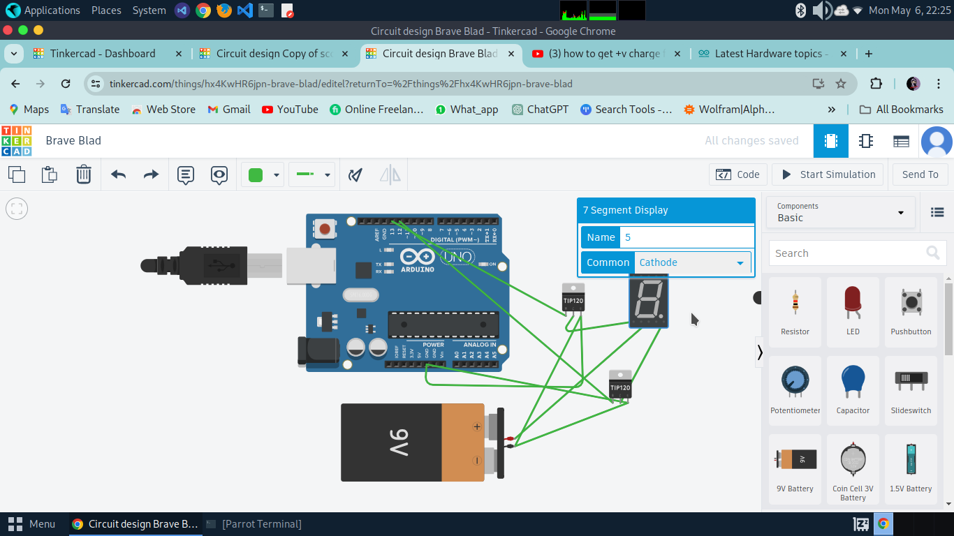
I only wanted to know how to connect and control a cathode 7 segment display with a transistor(TIP120) or i just wanted to know how to get +ve charge from collector of the transistor. please help!
Do you mean transistor and not transmitter?
Do you mean voltage and not charge?
The TIP120 is a two transistor (Darlington pair) and is not suitable for what you want to do with it. this is the data sheet for the device:- TIP120.pdf (534.6 KB)
It is against the forum rules to make duplicate posts, I have flagged the moderators about this.
Then why mark that post as a solution?
I think you would be better off posting a section that deals with a language closer to your own native language.
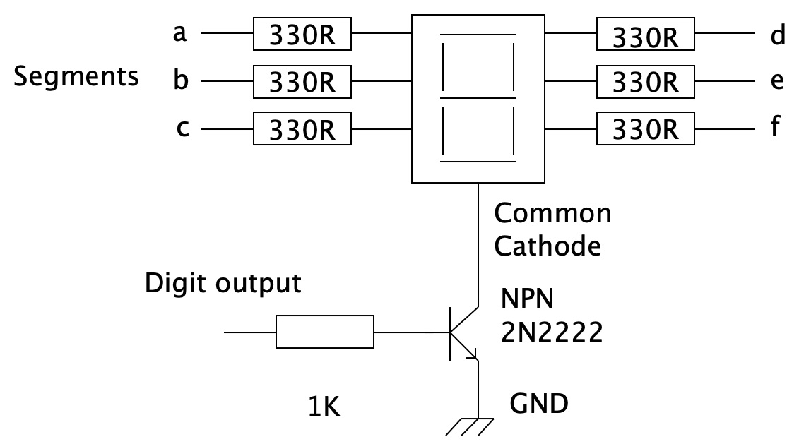
But the current limiting resistors must be in the segments. I am assuming that each segment doesn't want 500mA.
Also note you can't get this much current from the 5V on the Arduino. So using a battery or external supply then you must connect the negitave side of the supply to the GND pin of the Arduino.
When you wrote the word yesturday did a row of red dots appear under the word? That tells you that you made a spelling mistake. Press the control key (ctrl) and left click, then a list of alternatively words will come up for you to chose the right one.