I need to power up an aircon compressor which has a motor of 600w powered by 2V 3 phase AC. The controller supplied with the motor/compressor kit has failed, one phase missing and it occurs to me that I could achieve a lot by controlling the unit with an Arduino instead of a proprietary box with almost no smart ability. I have little or no experience with power electronics and at 66 yrs old, reluctant to learn this, my background is 40 plus years of PLC design, and I have never seen such a peculiar power spec for a motor, any ideas welcome!!
Do you still have the DC supply for the unit? Must be pretty massive to supply that much current at 2 volts!
1 Like
600AH of lithium batteries
And the batteries are in parallel and measure 2 volts on your meter?
1 Like
Try contacting the distributor or manufacturer. It is probably a bad label.
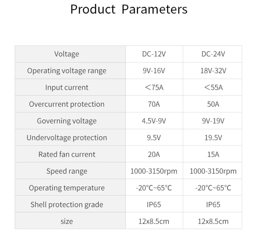
Lets look at it this way, the spec in the system declares it is 600w when run on 12vdc and 800w when run on 24vdc supply. I track and record battery voltage and current, and i know the system draws 51A when running, and the supplied controller is missing one phase output, i have measured 2v across the other 2 phases. Now this is very hard to believe as the 6mm motor cable would be carrying 300A and it ought to get rather warm, and i should have noticed this. However it is more believable that the system uses a 2v pulse to test the motor, perhaps the normal motor supply, is going to be 20V, which makes a little more sense, but it does not change my problem, i am still looking for a VFD type device that i can control with an arduino
OK so after a bit more time and digging I have discovered that the controller I would like to emulate with an Arduino, in fact uses 12 Mosfets to switch each phase from one polarity to the next in a sequence that emulates AC. the end result is not 2v AC at all but rather it seems it should be between 4.5v and 9v and I am betting that with a 12V supply the controller will output 4.5VAC, with 24V supply, 9VAC, and that the 2v output I measured is in fact as a consequence of a failure.
Now my question has changed somewhat but at least it is making more sense now, as the 2v output didnt.
Will I be able to emulate this AC using an Arduino to switch 12 Mosfets?
I am not yet sure why 12 are necessary, when logic tells me 6 should do the job, but I still need to put a magnifying glass on the faulty circuit board and see if it sheds more light.
I know the PWM outputs can reach 980HZ but I dont think they help me as there aren't enough of them and synchronizing them to be 120 degree out of phase seems unlikely, so then, using ordinary digital outputs, how fast a "frequency" would one be able to generate?
Is there an easier way, replacing the failed controller isn't an option, I am trying to move forward here, just trying to get help before I waste a lot of time and money on a quest for an impractical destination
An Arduino Uno is not well suited to 3 phase control, but can be done. There are many examples on the web. Basically you use all 3 timers to generate 3 complementary outputs. Phase control is performed by software.
600W @ 9V doesn't make sense, for a 3 phase motor that would be near 40 Amps per phase. Post the motor's data plate info and / or datasheet or other info you can find for the motor. Even a picture (with the data plate visible) might help.
Actually it is 9v when running off 24v supply, on 12v supply it is 4.5v and draws 50A
Well, It does now. ![]() An automotive / vehicular application?
An automotive / vehicular application?
Aircon, scroll compressor
This topic was automatically closed 180 days after the last reply. New replies are no longer allowed.