I have this piezo buzzer and although the current consumption of the buzzer is likely very very small, I tried using an N-MOSFET with a low gate-to-source turn-on voltage (like 1-2.5V max Vgs) to drive it as shown in the attached schematic. However, when I play a tone it's way more muted than driving it directly from the IO pin (I am using a 3.3V Arduino).
My question is, why is this the case? Shouldn't the tones be about the same volume with or without the MOSFET?
That MOSFET requires 5V minimum gate voltage to be fully switched on.
tried using an N-MOSFET with a low gate-to-source turn-on voltage (like 1-2.5V max Vgs)
Makes no sense. max Vgs would be like +/-20V or something like that.
I think you might mean Vth (threshold voltage), being the voltage below which the MOSFET is hard off - its
completely irrelevant to turning fully on.
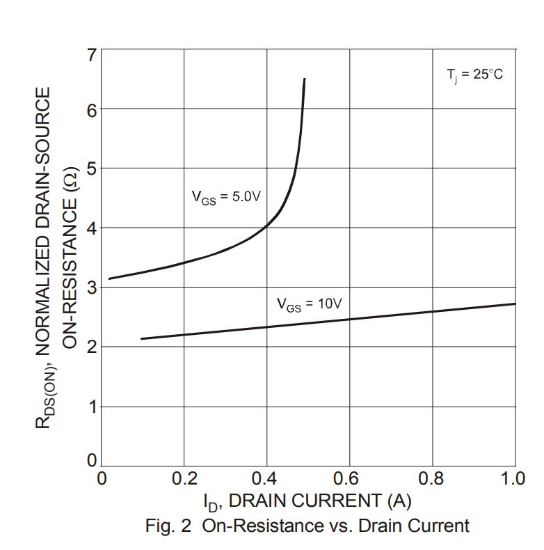
Look for the Rds rating - a value or values will be quoted each with a Vgs specified - those Vgs are
the gate voltages corresponding to the device being fully on.
I don't see the need for a mosfet. True piezos buzzers (the one you have) run on fumes.
Try connecting the piezo directly, and through a 470ohm (or even 1k) resistor to the pin.
Note that there is very little difference in volume.
Piezo volume depends on drive voltage.
You might want to try the toneAC library, with the piezo connected between two pins.
This push-pull configuration generates twice the voltage for the piezo.
Can still use that ~470ohm series resistor to make it easier for the pins.
Leo..
Weird thing is I tried just setting the gate voltage to HIGH (3.3V) and it does indeed put the low side of the buzzer to 0V as it's supposed to. I'm starting to think the tone() library and frequency stuff is what's causing it to not work too well? However, the spec sheet says delay time is in the order of <10ns.
The problem you're having is that a piezo is a capacitor.
That is being charged the first time the drain gets LOW.
There is no pull up mechanism, like you have on a normal digital pin.
So the piezo capacitor doesn't get discharged.
Your circuit will work if you put a (1k) resistor across the piezo.
Leo..
Thanks! I tried putting a resistor in parallel with the buzzer and it worked! However, I'm most likely just going to direct drive it without any resistor in series since it probably draws a couple electrons at a time like Wawa said.
I was looking at this schematic for a DIY reflow oven controller and they control their buzzer with a small signal NPN (I am assuming their buzzer isn't a piezo, but a polarized one). Also, I have no idea why they would control the SSR input with the same NPN if it only draws about 5mA?
Another issue: I tried using the 2N7002 to drive an SSR input, and even though the gate was set to a steady 3.3V the output of the SSR (an AC night light) flickered a lot and the input (the negative, switched input of the SSR) fluctuated on my multimeter. (As a quick verification I also bypassed the MOSFET with the 3.3V directly to the SSR input and it was steady.). What's could be causing this flickering?
androidfanboy:
I was looking at this schematic for a DIY reflow oven controller and they control their buzzer with a small signal NPN (I am assuming their buzzer isn't a piezo, but a polarized one). Also, I have no idea why they would control the SSR input with the same NPN if it only draws about 5mA?
Another issue: I tried using the 2N7002 to drive an SSR input, and even though the gate was set to a steady 3.3V the output of the SSR (an AC night light) flickered a lot and the input (the negative, switched input of the SSR) fluctuated on my multimeter. (As a quick verification I also bypassed the MOSFET with the 3.3V directly to the SSR input and it was steady.). What's could be causing this flickering?
Note the + and - on the buzzer.
That's not a piezo, but a DC buzzer (one that makes a beep by itself).
The 2N7000 is not really suitable for 3.3volt logic.
A normal NPN transistor might do better.
What 3.3volt Arduino are you using. SSR relays usually don't require that much drive current.
Can't you drive it directly with the pin.
Leo..
Just curious: why are 2N7000's not suited for 3.3V logic, and what makes a MOSFET suited for these sorts of applications? I normally just look for a low gate threshold (below 3.3V) and a max continuous drain to source current that will be sufficient for what it's driving. Is there something else I should be looking for when picking a MOSFET for these sorts of loads?
To answer your question, I'm using an ATmega32u4 at 3.3V. And yes, I can drive it directly (and I plan on doing so), but I just wanted to give the MOSFET a try just to see what happens. Why did the schematic I attached use a transistor to switch the SSR? Is there a particular reason for it? 5mA is a pretty small amount for any MCU.
Also, if I wanted to, say, use 5V instead of 3.3V (MCU logic VCC) as input to the SSR, this means I would have to use a transistor/MOSFET. What sort of component would you suggest? Is the 2N3904 going to do the trick? I still have no clue why the MOSFET output would flicker.
It was not designed for switching at low voltages.
Look for MOSFETs where "logic level" is specifically stated in the data sheet. Or, look at the specs for Rds(on) and the gate voltage (Vgs) at which that value holds. You want that Vgs to be less than 3V (ideally 1.5 to 2V) for use with 3.3V logic.
Most SSRs are designed for 3-32V switch input voltages, and may not work well at the lowest end of the range.
The 2N7002 has threshold voltage of 1.0-2.5V (min-max), so that shouldn't really be an issue right? Also, in the case of the buzzer I put a solid 3.3V across the MOSFET gate and it indeed drove the buzzer's "negative" end to GND. However, for the SSR it oscillates, which is confusing me.
Also, the ATmega32u4 is rated at around 40mA max on a single pin, 20mA continuous is safe.
OK, I'll try to find a different one with "logic level" specifically mentioned. However, I know that the SSR operates well at 3.3V because when I bypass the MOSFET there is no flickering at all.
With the 3.3V output of the ATmega32u4 on the MOSFET gate, I get fluctuating voltage on the MOSFET output (should be 0V since I am pulling it to GND, but it's like 0.3V to 2V on my multimeter). I tried using other IO pins on the board, and same thing. By itself the IO pin gives out a constant 3.3V, but when I plug it into the MOSFET gate, it fluctuates, and the MOSFET output reflects this fluctuation.
I also tried setting the IO pin to LOW and connecting it to the negative side of the SSR while its positive end was at 3.3V, and I measured a fluctuating 0V-0.2V at the negative end.
Connecting the MOSFET gate to GND (not LOW on the IO pin) yields a constant 2.5V on the MOSFET output. Not sure why it wouldn't be closer to 3.3V?
Connecting the MOSFET gate to 3.3V (not HIGH on the IO pin) yields a constant 0V on the MOSFET output, as expected.
Why would the 3.3V logic HIGH scenario cause flickering of the SSR input (MOSFET output)? To me it sounds like the SSR is the culprit.
The 2N7002 has threshold voltage of 1.0-2.5V (min-max), so that shouldn't really be an issue right?
You are NOT paying attention. The threshold voltage is of no interest to us. Please read reply #13 more carefully, and study the data sheet.
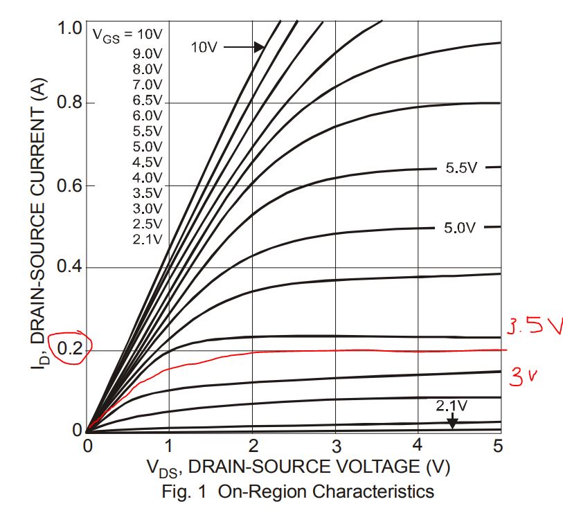
In particular, take a look at this graph of the 2N7000 drain-source voltage/current characteristics. Note especially the lines corresponding to different Vgs voltages.
I was looking at this schematic for a DIY reflow oven controller and they control their buzzer with a small signal NPN
What you might have missed is they are using 5V for the piezo and SSR. Since the logic is only 3V, the transistors are used to control that 5V and perhaps allow for more current. The Uno allows for up to 40mA sourced from it's I/O pins, but most 3V controllers are much less than that. I've been playing with a 32U4 board from Adafruit, and it's limits are 10mA.
As for your mosfet issue, you might measure voltage across the source drain while you think it's ON (it's not). It is acting as a resistor, and you can use ohm's law to fill in the blanks, and also see what would happen if you increase the voltage. Use it as a learning experience.
@jremington: If you look at the 2N7002 (the one I am using, which I linked previously), here is the graph, and at 3.3V Ids is about 200mA, and the SSR draws about 5mA. I still don't see an issue here.
I still have no idea why you're saying that the threshold voltage is of no interest to us at all. The lower Vth is, the lower the resistance will be at 3.3V, and the higher the Ids current will be. Simple as that right? For example, this MOSFET has "ultra low drive voltage" (1.2V Vth) and therefore at 3.3V it's fully "ON" (low resistance). Can you please explain what you meant by your bold statement about Vth?