DRV8833 DC Motor driver not driving motor/outputting voltage

Hi all,

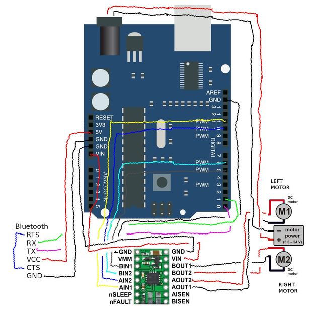
For my project, I am trying to drive a DC vibrating motor with the DRV8833 breakout (from Adafruit, pictured below) but my motors won't run. My voltmeter isn't reading any voltage from its AOUT pins. I've tried hooking it up to various sizes of DC motors as well to no avail though I know the motors work fine because they run when simply hooked up to batteries.

I've tried various wiring diagrams similar to the pics attached, and two different codes. I might be wrong, but from my understanding to run the motors via the DRV8833, one should digitalWrite high to one pin and low to the other:

#define AIN1 5
#define AIN2 6

void setup() {
  pinMode(AIN1, OUTPUT);
  pinMode(AIN2, OUTPUT);
  Serial.begin(9600);
}

void loop() {
  Serial.println("MOTOR ON");
  digitalWrite(AIN1, HIGH); //run motor
  digitalWrite(AIN2, LOW);
  delay(3000);
  Serial.println("MOTOR OFF");
  digitalWrite(AIN1, LOW);  //stop motore
  digitalWrite(AIN2, LOW);
  delay(3000);
}

I also tried an example code from a DRV8833 library:

/*
 * DRV8833_Test
 * Simple test for the DRV8833 library.
 * The DRV8833 is a dual motor driver carrier made by Pololu.
 * You can find it here: https://www.pololu.com/product/2130
 *
 * Attach the positive wire of a motor to the Aout1 and the negative
 * wire to the Aout2 pins on the DRV8833.
 * Attach the Arduino's ground to the one of the GND pins on the DRV8833.
 * Attach a 9V battery's positive connection to the Vin pin
 * on the DRV8833, and the negative connection to one of the GND pins.
 * 
 * Created March 16, 2015, by Aleksandr J. Spackman.
 */

#include <DRV8833.h>

// Create an instance of the DRV8833:
DRV8833 driver = DRV8833();

// Pin numbers. Replace with your own!
// Attach the Arduino's pin numbers below to the
// Ain1 and Ain2 DRV8833 pins.
const int inputA1 = 5, inputA2 = 6;

void setup() {
  // put your setup code here, to run once:
  
  // Start the serial port:
  Serial.begin(9600);
  
  // Wait for the serial port to connect. Needed for Leonardo.
  while (!Serial);
  
  // Attach a motor to the input pins:
  driver.attachMotorA(inputA1, inputA2);
  Serial.println("Ready!");

}

void loop() {
  // put your main code here, to run repeatedly:
  
  Serial.println("Forward:");
  // Put the motor in forward:
  driver.motorAForward();
  // Wait to see the effect:
  delay(500);
  
  // Pause the motor for stability:
  driver.motorAStop();
  
  Serial.println("Reverse:");
  // Put the motor in reverse:
  driver.motorAReverse();
  // Wait to see the effect:
  delay(500);
  
  Serial.println("Stop:");
  // Stop the motor:
  driver.motorAStop();
  // Wait to see the effect:
  delay(500);

}

I doubt the breakout is faulty though I'm not sure how to verify that; I feel that the problem lies in my wiring, power supply, or code. A definite wiring diagram for my Arduino-DRV8833-motor system would be greatly appreciated if possible as I'm still very lost about which diagram to follow.

Thanks in advance for any help! I've been struggling to run this motor for a while now; though I'm unsure of the voltage/current draw of my motor, it is the one in the picture attached.

drv8833.png

though I'm unsure of the voltage/current draw of my motor

You have to know those. Post a link to the motor product page or motor data sheet.

How are we supposed to guess what all the different wiring diagrams mean? Post your own, accurate, hand drawn wiring diagram, with pin numbers and connections carefully labeled, and give details of the motor power supply. Do not attempt to power motors or servos from the Arduino 5V output.

As suggested in Reply #1, plus ...

Also, please display your image(s) in your post so we can see it(them) without downloading it(them). See this Simple Image Guide

What motor power supply do you have (volts and amps_? Be aware that the max voltage for a DRV8833 is 10.8v

I use DRV8833 drivers and have had no problem with them.

...R

Robin2:
Also, please display your image(s) in your post so we can see it(them) without downloading it(them).

Done, sorry about that I'm new to forums.

Robin2:
What motor power supply do you have (volts and amps_? Be aware that the max voltage for a DRV8833 is 10.8v

jremington:
You have to know those. Post a link to the motor product page or motor data sheet.

I'm not sure what voltage my power source will be yet but I measured my motor's resistance to be 21 ohms. Speaking of power source,

Robin2:
I use DRV8833 drivers and have had no problem with them.

If you don't mind sharing, how did you set yours up? wiring and all. And is it possible to power the breakout/motor with just the Arduino's 5V output? My project is very small and has limited space for any large external power sources.

jremington:
Post your own, accurate, hand drawn wiring diagram, with pin numbers and connections carefully labeled, and give details of the motor power supply.

I've tried the various configurations of wiring diagrams but currently have exactly this setup, but with one motor.

Is this wiring diagram correct? If it is, is my code for running the motors correct?

Thanks in advance.

Seems silly to use a H-bridge for a simple vibrating motor.
A simple transistor and a kickback diode across the motor could be enough.
Leo..

I'm not sure what voltage my power source will be yet but I measured my motor's resistance to be 21 ohms

Not enough information. Try running the motor for a while at 5V (NOT the 5V Arduino output). If the motor works well and does not become hot to touch, fine.

Typical simple motor driver circuit:

jremington:
Not enough information. Try running the motor for a while at 5V (NOT the 5V Arduino output). If the motor works well and does not become hot to touch, fine.

Typical simple motor driver circuit:

Ran the motor with 5V. Measured the voltage draw to be around 4.8V; consequently, the current draw was 0.23A. Motor works well and does not get hot.

Unfortunately I am but a high school student who has only some surface level knowledge of Physics C circuitry so I don't fully understand what's going on in your "simple" circuit. I'm not nearly at the level of what you guys imply as simple or common sense so if you could kindly explain it, it'd be greatly appreciated.

I am having trouble finding a specific wiring diagram to follow and verifying if my code is okay-- as mentioned in my last two posts-- so if anyone can provide some insight on that it'd be awesome.

Thanks for your replies, I am still learning so they help a lot.

A simplified version of the MOSFET motor control circuit is diagrammed and explained in this tutorial: https://www.quora.com/How-do-I-use-a-MOSFET-to-break-a-12-20-v-circuit-using-5v-signal-from-Arduino but we strongly recommend to use a 180 to 220 Ohm resistor (R2 in the diagram of reply #5) between the Arduino output pin and the gate of the transistor. Otherwise you can damage the Arduino port pin.

If you have questions about that tutorial, or the circuit I posted, feel free to post them here.

genthehuman:
If you don't mind sharing, how did you set yours up? wiring and all.

I don't have any diagrams to share. I just followed the Pololu wiring diagram which (I think) is the image you have posted.

I don't understand the grey block between the motors in your diagram - why is it located between the motors? And it seems to say 5.5v to 24v. 24v would be much too high for an Arduino or for a DRV8833.

The Vin pin on the DRV8833 is not intended to be connected to the Arduino Vin pin - it is just a coincidence that they have the same name. The motor power supply should be connected to Vin on the DRV8833.

If you want a simple power supply for both the motor and the Arduino I suggest you use a pack of 3 x AA alkaline cells (4.5v) or a pack of 4 x AA NiMh cells (4.8v) connected to the Vin on the DRV8833 and to the 5v pin on the Arduino.

...R

PS ... I agree with those who have said that a DRV8833 is overkill for a vibration motor - but if you already have it then it may be convenient to use it.

So I don't Know if any one has spotted this yet but...

he seems to have his VIN from the DRV8833 connected to the VIN of the Arduino. This may very well be the reason he has no output to his motors. Their is no current flow to the motors by connecting them this way.
He dose have the correct connections for controlling the driver properly. He just needs to actually have power going to the motors. VIN is for power to flow into not out of. The solution is to connect the VIN of the DRV8833 to either the same voltage sources the arduino or a separate power supply, baring in mind that the grounds need to be sheared between the arduino and the DRV8833 either way.