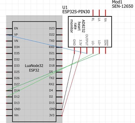
I am trying to generate proper ECG graphs using ESP32 with 30 pins and AD8232 heart rate monitor. After several attempts, I am failing to get proper ECG graphs. Can't figure out what is going wrong here. Are the ecg electrodes placed wrong or what is happening? Can anyone kindly help? I have a deadline to meet. Attaching my graph screenshot.
I don't manage to magnify the X scale. Never mind. The signal doesn't look lika an electrocardiogram at all. It looks like a sina curve likely picked up from mains.
I suggest You post the schematics and also try google on "Arduino + ECG". There are several projects like Yours.
Are you following a tutorial?
Could you please post your code in code tags, and a diagram of your actual hook-up of the components to the ESP
An ECG is a graphical representation of the electrical activity of the heart and requires at least 2 points on the body. A standard ECG uses 12 leads. Normally the signal is filtered as electrical activity in other muscles can cause artefact. Your trace does not look like the subject is still alive
Thank you so much for your reply. Here is my circuit diagram. I am new to this. So any suggestions would be really helpful.
Yes I am following some. But those are a little different
Thank you so much for your feedback. I am trying to get it right.
My code:
void setup()
{
// initialize the serial communication:
Serial.begin(9600);
pinMode(14, INPUT); // Setup for leads off detection LO +
pinMode(12, INPUT); // Setup for leads off detection LO -
}
void loop() {
if((digitalRead(14) == 1)||(digitalRead(12) == 1)){
Serial.println('!');
}
else{
// send the value of analog input 0:
Serial.println(analogRead(A0));
}
//Wait for a bit to keep serial data from saturating
delay(1);
}
Edit ![]() code into code tags <|>. Give description of how you obtained trace. Your circuit diagram is incomplete and would not create any output
code into code tags <|>. Give description of how you obtained trace. Your circuit diagram is incomplete and would not create any output
I am connecting the ESP32 with micro-usb port with the laptop for powering. Not much sure what you mean. ![]()
A human presumably is in the circuit
Yes I am using the 3 lead ecg electrodes on me. How do I possibly show that in the diagram?
Fritzing are poor but I would add a lead with a label on a schematic stating electrode for right wrist etc
Okay. I would do that. Thank you for your feedback. Apart from that, are the connections okay?
Link to the sensor
https://learn.sparkfun.com/tutorials/ad8232-heart-rate-monitor-hookup-guide/all
There are countless ESP32 boards - do you know which one you have? (hint - give a link)
Generally the pin marked VP is analog input ADC1 ch 0 on GPIO36
There is a good tutorial here on reading an analog voltage with the ESP32
I'd suggest you connect a pot as shown and try it. You could use GPIO36 instead of GPIO34 as the tutorial uses.
Thank you for your post. It was very helpful.
This topic was automatically closed 180 days after the last reply. New replies are no longer allowed.


