Hi all,
I just wanted to show that I finally finished the electronic cat door that I started last year. I started a thread at the old forum a while back:
http://arduino.cc/forum/index.php/topic,20190.0.html
And now wanted to show the (almost) finished project:

I say it's almost finished because I'm having a strange problem with it intermittently. Sometimes after the door comes up, hits the upper limit switch, it doesn't go back down. ![]() And even less, it will not open after you hit the button. And once or twice, after it came back down, the servo kept spinning even though the acrylic cover hit the lower limit switch.
And even less, it will not open after you hit the button. And once or twice, after it came back down, the servo kept spinning even though the acrylic cover hit the lower limit switch.
I wouldn't think it's the code, because what's weird is that I can pull the circuit board I made and bring it back into my room and test it pretty extensively, and it never seems to fault. See this video: Electronic Cat Door Standalone Board Complete - YouTube
But just in case, here's the code:
// Controlling a full rotational servo

// Attach red wire of servo to TO SEPARATE POWER SUPPLY
// Attach black wire of servo to GND on Arduino
// Attach control wire of servo to pin 9 on Arduino


// constants won't change. They're used here to
// set pin numbers:
const int buttonPin = 2;    // the number of the pushbutton pin
const int topLimitSwitch = 4; // the upper limit switch
const int bottomLimitSwitch = 8; // the lower limit switch
const int ledPin =  13;     // the number of the LED pin (Currently not used)

// Variables will change:
int ledState = LOW;         // the current state of the output pin
int lastButtonState = LOW;  // the previous debounced button state
int lastReading= LOW;       // the previous reading from the input pin
int speakerOut = 6;         // piezo

// the following variables are long's because the time, measured in miliseconds,
// will quickly become a bigger number than can be stored in an int.
long lastDebounceTime = 0;  // the last time the input pin was toggled
long debounceDelay = 50;    // the debounce time; increase if the output flickers


int servoState = 1500; // the current state of the servo

#include <Servo.h>

Servo myservo;  // create servo object to control a servo


void setup()
{
  myservo.attach(9);  // attaches the servo on pin 9 to the servo object

  pinMode(buttonPin, INPUT);
  pinMode(topLimitSwitch, INPUT);
  pinMode(bottomLimitSwitch, INPUT);
  pinMode(ledPin, OUTPUT);

  pinMode(speakerOut, OUTPUT);
}

void loop()
{

  //myservo.writeMicroseconds(1500); //stay idle

  //myservo.writeMicroseconds(1500); //
  //Serial.print("Running motor at: ");


  // read the state of the switch into a local variable:
  int reading = digitalRead(buttonPin);

  // read the state of the upper and lower limit switches into a local variable:
  int upperSwitchReading = digitalRead(topLimitSwitch);
  int lowerSwitchReading = digitalRead(bottomLimitSwitch);

  // check to see if you just pressed the button
  // (i.e. the input went from LOW to HIGH),  and you've waited
  // long enough since the last press to ignore any noise:

  // If the switch changed, due to noise or pressing:
  if (reading != lastReading) {
    // reset the debouncing timer
    lastDebounceTime = millis();
    // save the reading.  Next time through the loop,
    // it'll be lastReading:
    lastReading = reading;
  }

  if ((millis() - lastDebounceTime) > debounceDelay) {
    // whatever the reading is at, it's been there for longer
    // than the debounce delay, so accept the button changed state:

    // toggle the LED if the state of the button changes from LOW to HIGH:
    if (lastButtonState == LOW && reading == HIGH) {
      /*if (ledState == HIGH) {
        ledState = LOW;
        //servoState = 1520;
        // The below line will stop the servo - we don't need to use this if/then bracket anymore as it is not how we want it to work
        //myservo.writeMicroseconds(1500);
     } else {
        ledState = HIGH;
        //servoState = 3000;
        //myservo.writeMicroseconds(500);
      }

      digitalWrite(ledPin, ledState);
      */


      // MAIN CODE GOES HERE

      // Turn on servo clockwise to raise cover until it hits the upper limit switch
      while (digitalRead(topLimitSwitch) == LOW) {
        myservo.writeMicroseconds(3000);
      }

      // Make servo be idle again
      myservo.writeMicroseconds(1520);

      // Wait 8 seconds
      delay(8000);


       // beep 5 times to give the cat a warning before closing door
        for (long i = 1; i < 6; i++)
        {
          analogWrite(speakerOut,128);
          delay(250);
          digitalWrite(speakerOut, LOW);
          delay(250);
        }


      // Turn on servo couter-clockwise to lower cover until it hits the lower limit switch
      while (digitalRead(bottomLimitSwitch) == LOW) {

        // ok, now close the door (rotate servo counter-clockwise)
        myservo.writeMicroseconds(1300);

        //digitalWrite(speakerOut,HIGH);

       /*   for (long i = 0; i < 2048 * 3; i++ )
        {
            // 1 / 2048Hz = 488uS, or 244uS high and 244uS low to create 50% duty cycle
            digitalWrite(speakerOut, HIGH);
            delayMicroseconds(244);
            digitalWrite(speakerOut, LOW);
            delayMicroseconds(244);
        }
        */

      }


      // Make servo be idle again
      myservo.writeMicroseconds(1520);


      // END MAIN CODE

    }
    lastButtonState = reading;
  }


}
When I originally 'completed' this project, I used CatIII twisted pair wires for the wiring, and it seemed the problems happened way too much, so I thought maybe it was the wiring. So I ripped all those wires out, and used 22 gauge solid copper wires (individual wires), then as you can see in the video, covered them with the white wire track. It did seem to get a lot better, but it's still happening. ![]()
Minus the power-indicating LED (and the resistor for it), and the filtering 100 uF capacitor, the following Fritzing file shows how I built my board:
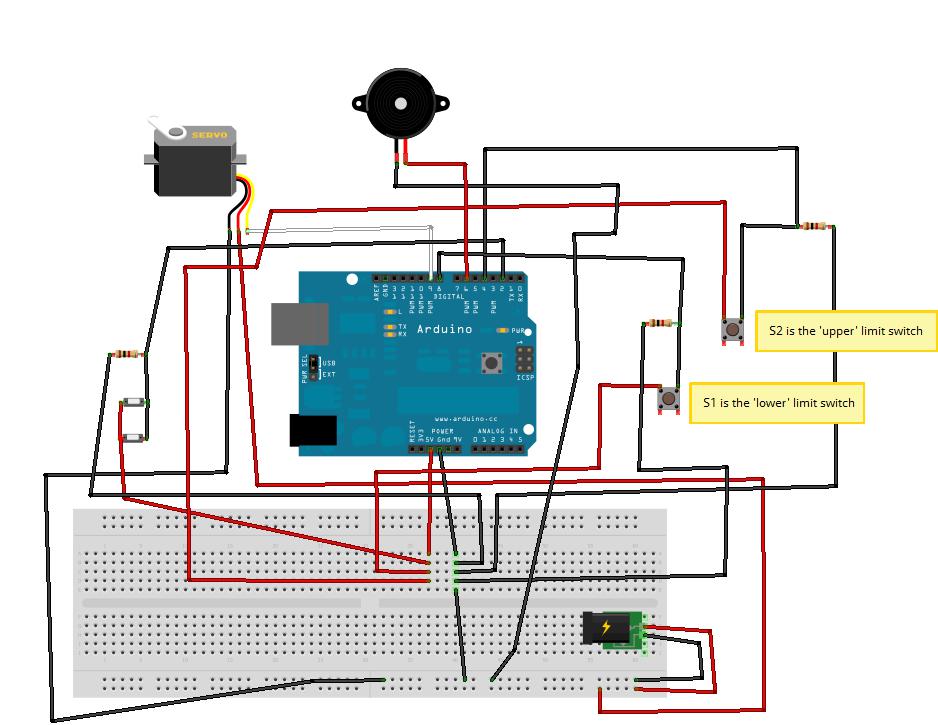
Do you think that my problems are because I didn't add a .1uF capacitor? Other than that, I have no ideas, and would love to get this project out of my hair so I can start my next Arduino project. ![]()
Thanks