Hello. I am having issues after following this video on PID motor control.
Video: https://youtu.be/pOFakaTQDXM?si=Vvpwa2LANOxi_RbT

My motor has 70 PPR and I followed the schematic attached.
When I keep the channel 1 and channel 2 encoder wires attached to the pins in the schematic in that order, the motor moves at 1000 RPM and does not change even after changing Kp. The serial monitor also says the motor is moving at 0 RPM and the serial plotter shows the RPM at zero.

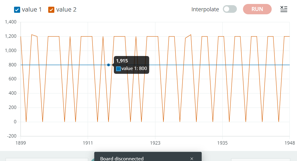
When I switch the order and connect channel 1 to pin 3 and channel 2 to pin 2, the motor switches between like 2000 RPM and zero. Despite changing the Kp values the plot barely changes and its stuck fluctuating between these values.

Here is the code I used:
//***********S KAED BEY************************************************
//***********MECHATRONICS ZOO******************************************
//****PID ANGULAR SPEED CONTROL FOR BRUSHED DC MOTOR UNDER NO LOAD*****
//***********ONE DIRECTION-CLOSED LOOP-USING ARDUINO UNO***************
//***********ENTER YOUR PID PARAMETERS BELOW***************************
float kp=0.01;    //change value of Kp
float ki=0.0;   //change value of Ki
float kd=0.0;   // change value of Kd

//****************TIME VARIABLES**************************************
unsigned long t_now;
unsigned long t_prev = 0;


//****************INTERRUPTS PINS*************************************

// If you use interrupts, you have to use pins 2 and 3 in UNO, NANO, MINI..
// Using the interrupts, we will calculate the rotation direction-
//if needed, count the encoder pulses and caluclate the angular speed (rpm)
const byte interruptPinA = 2;
const byte interruptPinB = 3;

//****************COUNTER VARIABLE************************************

//This is the variable allocated for counting the pulses from the encoder
//every time the motor rotates
volatile long EncoderCount = 0;


//*************UNO OUTPUTS --> L298 BRIDGE INPUTS*********************
const byte DirPin1 = 4;
const byte DirPin2 = 5;//DirPin 1 and 2 will decide the motor rotation direction
const byte PWMPin = 6; // This pin will control the Motor speed via PWMval
int PWMval=0; // Initial PWMval is set to zero, this value is the PWM duty cycle
              // from 0 to 255

//****************ENCODER PULSES************************************
//int PPR=70; Pulse Per Rotation-Measured manually-see youtube video

volatile unsigned long count = 0;
unsigned long count_prev = 0;

//***************************RPM***********************************
// Theta is the angular position
//Theta_now and Theta_prev are both needed to calculate the RPM (rounds per minute)
//RPM can be calcuated as the difference in position with respect to time
float Theta_now;
float Theta_prev = 0;

//RPM_input is the user input RPM (set value)
//RPM_output is the motor output RPM as measured by the encoder
float RPM_output, RPM_input;
int dt;                      // Period of time used to calcuate RPM
float RPM_max = 1000;         // Setting up a safe maximum RPM for the Motor

//******************************MISC VARIABLES*****************
#define pi 3.1416
//Maximum motor voltage in clockwise rotation
float Vmax = 6;      // Check Motor Datasheet
//Minimum motor voltage
float Vmin = 0;
//Initialize motor input voltage value to zero
float V = 0;         // set initial voltage to zero
// Error signals and PID (proportional Integral Derivative) terms
float error_now, error_prev = 0, integ_now, integ_prev = 0;

//**********ISR FUNCTIONS*****************************************
//***********ENCODER A********************************************
//This is the pinA function,Interrupt Service Routine for pin A
// below is the logic for pinA
void ISR_EncoderA() {
  bool PinB = digitalRead(interruptPinB);
  bool PinA = digitalRead(interruptPinA);
// detecting if motor rotating clockwise
// if A is high while B is low, then direction of rotation is clockwise
  if (PinB == LOW) {
    if (PinA == HIGH) {
     EncoderCount++;
    }
   }

  else {
     if (PinA == LOW){
      EncoderCount++;
    }
  }
}

//**********ISR FUNCTIONS*************************************
//***********ENCODER B****************************************

void ISR_EncoderB() {
  bool PinB = digitalRead(interruptPinA);
  bool PinA = digitalRead(interruptPinB);

  if (PinA == LOW) {
      if (PinB == LOW) {
      EncoderCount++;
    }
  }

  else {
    if (PinB == HIGH) {
      EncoderCount++;
    }
    }
}
//*************************************************************
//***MOTOR DRIVER FUNCTION*************************************
//The below code takes the calcuated voltage V and maps it to an output PWM range from 0 to 255 (8 bit PWM resolution in UNO)
void WriteDriverVoltage(float V, float Vmax) {
  int PWMval = int(255 * abs(V) / Vmax);
  if (PWMval > 255) {
    PWMval = 255;
  }

  //setting motor direction
  digitalWrite(DirPin1, HIGH);
  digitalWrite(DirPin2, LOW);
  analogWrite(PWMPin, PWMval);
}
//*************INTERRUPT SERVICE ROUTINE*************************
ISR(TIMER1_COMPA_vect) {
  count++;
}
void setup() {
  //General setup

  Serial.begin(9600);
  pinMode(interruptPinA, INPUT_PULLUP);
  pinMode(interruptPinB, INPUT_PULLUP);
  attachInterrupt(digitalPinToInterrupt(interruptPinA), ISR_EncoderA, CHANGE);
  attachInterrupt(digitalPinToInterrupt(interruptPinB), ISR_EncoderB, CHANGE);
  pinMode(DirPin1, OUTPUT);
  pinMode(DirPin2, OUTPUT);

//***********INTERRUPT SETUP************************************
  cli();
  TCCR1A = 0;
  TCCR1B = 0;
  TCNT1 = 0;
  OCR1A = 12499; //Prescaler = 64
  TCCR1B |= (1 << WGM12);
  TCCR1B |= (1 << CS11 | 1 << CS10);
  TIMSK1 |= (1 << OCIE1A);
  sei();
}
//**************************************************************
//**************************************************************
//****************MAIN LOOP*************************************
void loop() {
  if (count > count_prev) {
    t_now = millis();
    Theta_now = EncoderCount / 70;
    dt = (t_now - t_prev);
    RPM_input = 800;       // This is the user input RPM

    //*********CONDITION OF OPERATION**************************
    //*********SWITCH MOTOR OFF AFTER A PERIOD OF NO INPUT*****
    if (t_now / 1000.0 > 100) {
      RPM_input = 0;
    }

    //***********ERROR AND PWM CALCULATIONS*******************
    //***********PID MOTOR TERMS CALCULATIONS*****************
    RPM_output = (Theta_now - Theta_prev) / (dt / 1000.0) * 60;
    error_now = RPM_input - RPM_output;
   integ_now = integ_prev + (dt * (error_now + error_prev) / 2);

   // Now calculating the Motor voltage or the PID controller ouput
    V = kp * error_now + ki * integ_now + (kd * (error_now - error_prev) / dt) ;

    if (V > Vmax) {
      V = Vmax;
      integ_now = integ_prev;
    }
    if (V < Vmin) {
      V = Vmin;
      integ_now = integ_prev;
    }
//*********************************************************
//*********************************************************
    //*******WRITING VOLTAGE TO L298***********************
    WriteDriverVoltage(V, Vmax);
     Serial.print(RPM_input);
     Serial.print(" ");
     Serial.print(RPM_output);
     Serial.print(" ");
     Serial.println();
    Theta_prev = Theta_now;
    count_prev = count;
    t_prev = t_now;
    integ_prev = integ_now;
    error_prev = error_now;
  }

}
//Enjoy