I have question for smarter minds than me. I am working on a project that at the moment has a DUE taking 3 buttons connected via ~30cm wires and 2 light sensors connected by ~4m wires. (that will be increased up to 6 or 7 push buttons connected via 30cm or so wire and ~20 light sensors via ~4m wires as well as a bunch of outputs as well hence the DUE).
On a bread board with short wires (5cm or so max) everything worked well and as expected. When i expanded to the 30cm and 4m wires I started to get errant button presses and sensor triggers due to EMI.
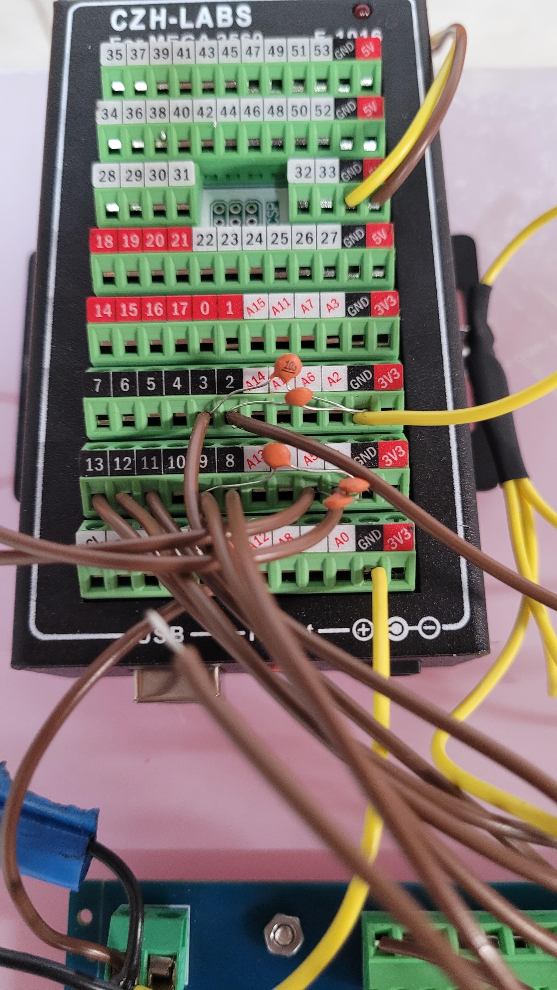
I know the general wisdom is to use shielded cable and i will probably go down this route with the final project but I found a 10 000pF capacitor wired from the signal headers to ground stopped all interference as shown in the attached picture.
I am considering just using the caps on all the pins (due to cost of shielded wire) but wanted to see if there was a better way to wire this rather than by plugging them into the headers like i have as it gets a bit unruly when i step up to 20-30 inputs.
Your buttons should be connected as active low, connected to a ground rail, with a pull-up to +Vcc
For your buttons you can use capacitor debouncing like this, which will also suppress EMI.
The buttons are wired low but definitely get errant emi presses with wire lengths greater than about 5cm.
The light sensors are actually flame sensor modules.
They can provide either analogue or digital signals. At the moment I'm using analogue and it suffers from EMI but seems to be fixed with the caps wired in at the headers to ground (Im not sure yet if this screws with the signal and flame sensing but seems to be working at the moment). I haven't tried the digital yet but think it will be the same.
I'm hoping there is a better way than wiring each header with caps
unless there is a VERY HIGH source of EMI that should not happen.
Is it possible there is a problem with the earth connection? Or could it be switch bounce?
yes, because the analog output is rather high impedance. The digital output isnt.
Can you explain? Maybe my below thinking is wrong.
I don't have the datasheet at hand for a SAM(D) processor, but for a AVR processor the IIL and IIH are 1 uA which would result in an input impedance of around 5 MOhm. I would call that rather high
It's possible that there is an earth connection problem but it happens with 3 separate buttons so don't think so. It's definitely not bounce as the buttons are not being pressed at all during testing. switching lights and nearby appliance on the same circuit, on and off will cause errant button presses, as will firing a spark plug (completely separate isolated battery supply so definitely EMI there).
Just tested the digital signal and while it is more stable it definitely still suffers from this EMI
Pins are set to input_pullup (also tried without and using an external pull-up) wires are hand twisted, not the best job but should be enough. Still suffers from emi
This code, 2m single wire one end permanently attached to PA0 (stm32f103 ) no interference even if touching the wire by hand, no antenna effect, LED responding when second end of the wire is touching the ground.
const int BUTTON = PA0;
const int LED = PC13;
int BUTTONstate = 0;

void  setup()
{
  pinMode(BUTTON,  INPUT_PULLUP);
  pinMode(LED, OUTPUT);
}

void  loop()
{
  BUTTONstate = digitalRead(BUTTON);
  if (BUTTONstate == LOW)
  {
    digitalWrite(LED, LOW);
  }
  else{
    digitalWrite(LED, HIGH);
  }
}
There are basically two types of EMI, radiated and conducted.
Conducted EMI travels through the wires, radiated travel through the air.
You may have one or the other or both.
If placing capacitors on all the connections solves the problem then exactly what are you looking for.
I was mostly asking to see if there could be a better way to fix this or at least to wire up the caps because 20+ caps on the headers becomes almost unworkable particularly when moving to the final design. A slight bump could cross pins and cause even more errant readings
The analog OUTPUT is from the flame sensor. Connected to an analog input (virtually infinite impedance) the connection is much more susceptible to EMI than a digital connection to the output of a comparator.
I'd suggest an external pull-up of about 1k, and a capacitor across the button contacts.
Have you got supply decoupling between vcc and ground? Is your ground a star point?
You should not be seeing EMI issues with short twisted wires.
I've recently been having to learn about contact wetting, so this leapt out
The current spike still occurs - but has a beneficial effect in keeping the switch contacts clean.
and you make a compelling case for hardware debouncing.
The minimum current for an Omron B3F series tact switch is 10 uA.
But good luck finding the spec for inexpensive look-a-likes, which I think mightn't be so good, that is to say the current must be substantially higher for long term reliability.
I will admit this comes as something of a surprise. Live and learn.