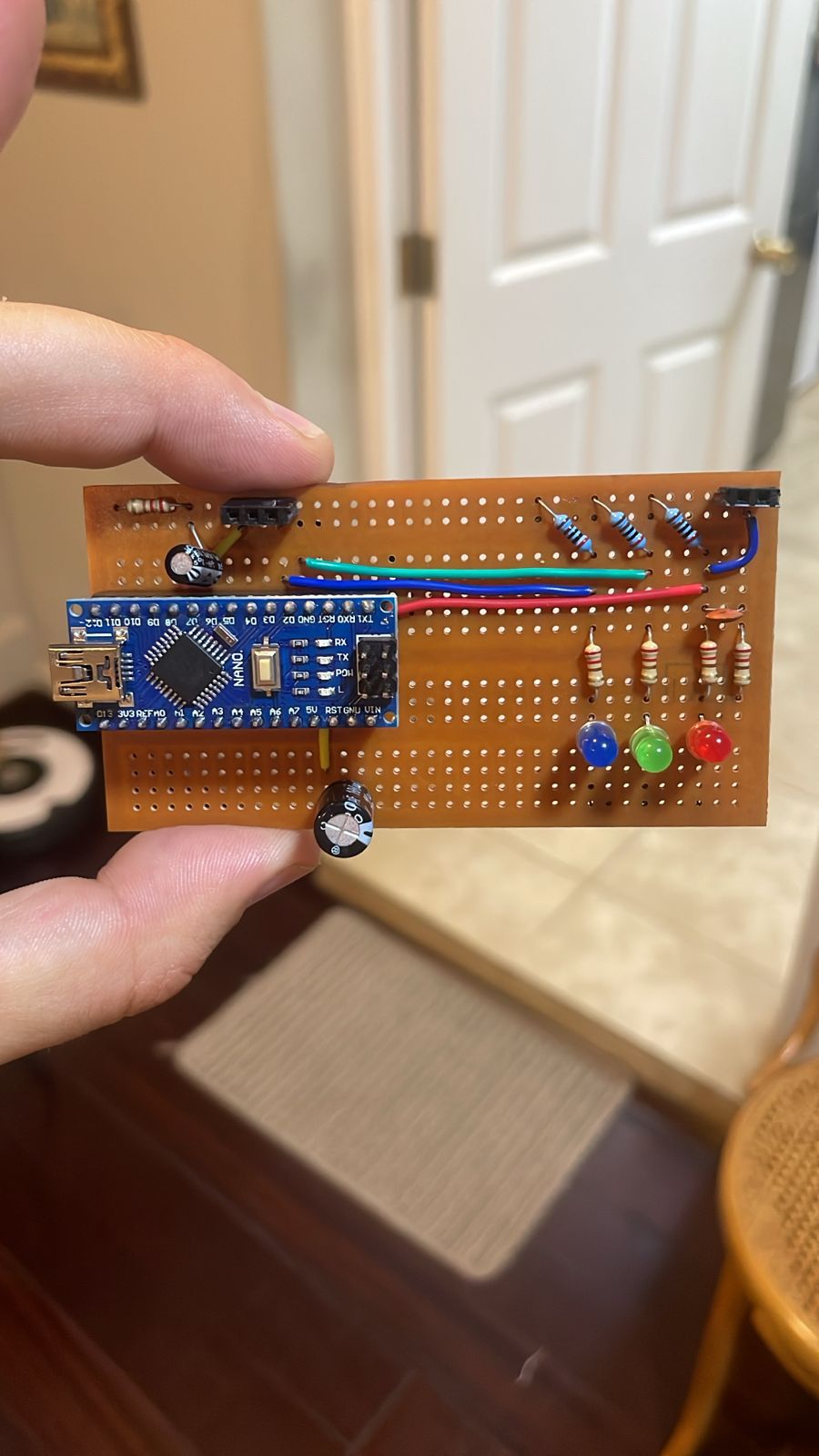
I am working on a control circuit for a humidifer in a shiitake mushroom growing room. That equipment consists of an AC motor that spins a disk spraying mist over the room, rated at 300W working under 220Vac. The arduino opens or closes the circuit via a solid state relay SSR25DA, based on the humdity read by the DHT sensor.
I have designed the four following stages:
Stage 1: Humidity below 75%. SSR is on. Red led on.
Stage 2: Uptrend from 75% to 85%, SSR on. Red led on, green led flashing.
Stage 3: 85% or more reached. Only blue light on. Relay is off.
Stage 4: Downtrend from 85 to 75%. Only green led steady.
Error code: upon NaN read by sensor: flash green.
The circuit failed when using the humidifier as a load, with error code.
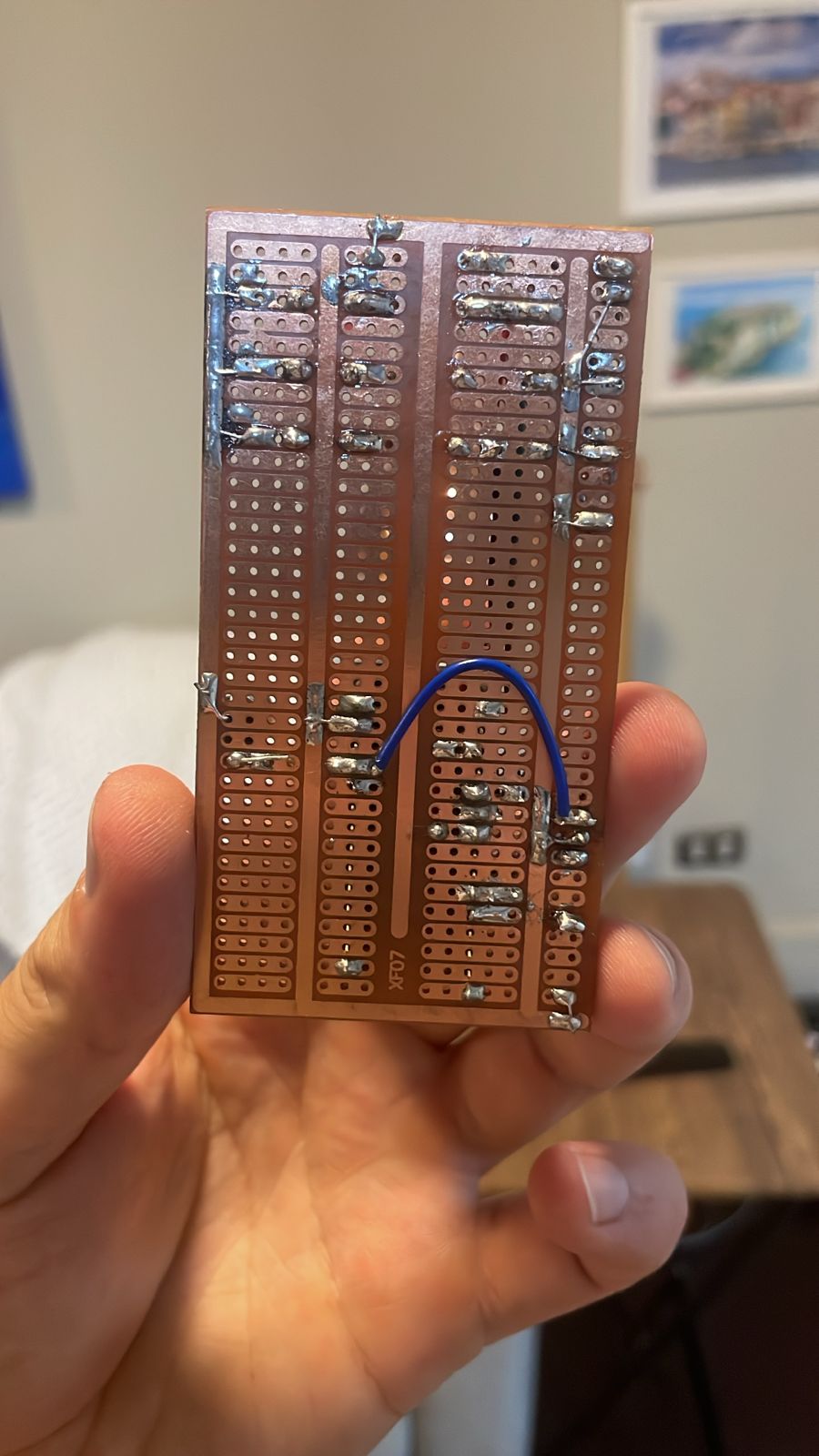
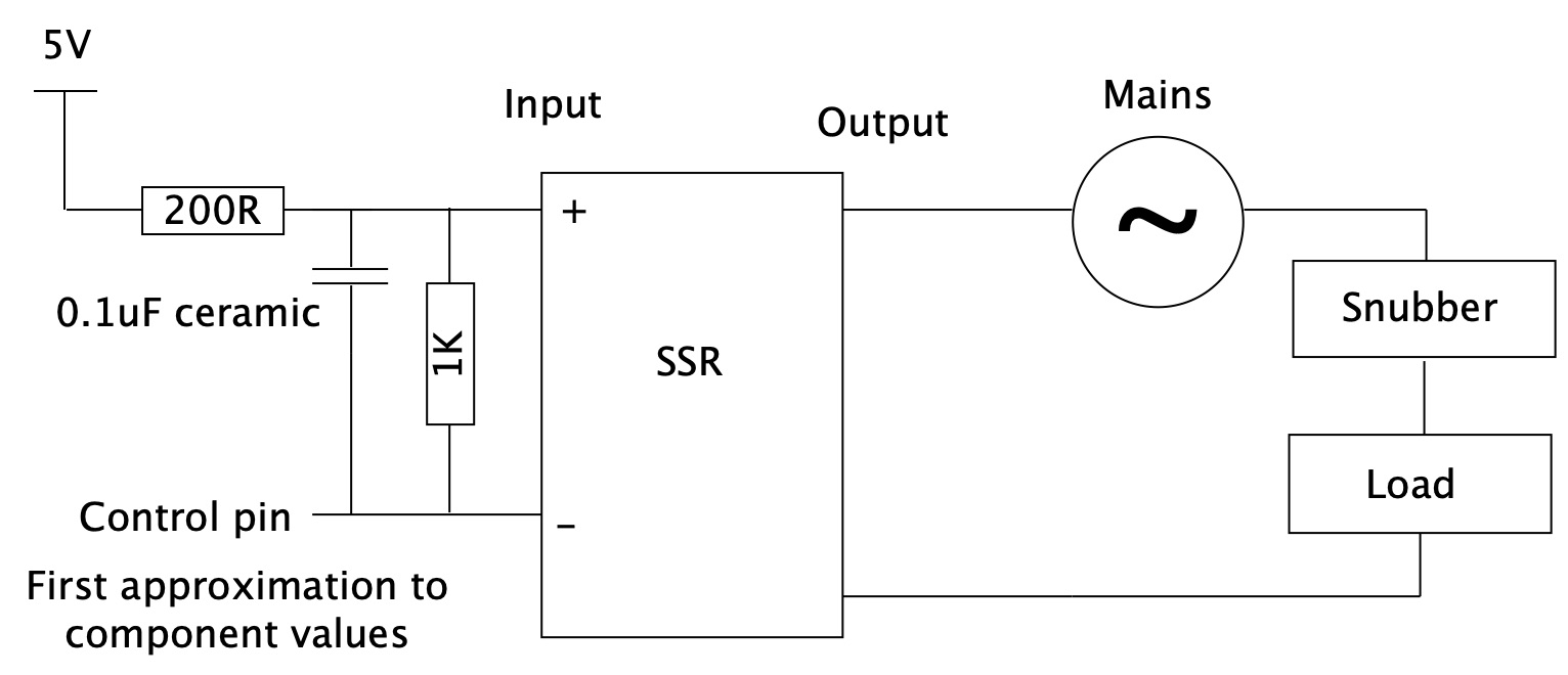
This circuit works fine with loads light a light bulb. I found that turning on the egg beater close to the circuit leads to the same error. This egg beater runs at 300W too. I added a snubber at the 5V terminals of the SSR. With this, i could run the egg beater to speed 4 (out of 5) with no failure. failing at 5. (when connected as load, at a distance of 5m of the arduino). This makes me think that maybe the mains cables themselves cause EMI on the arduino (distance = 0.5m from the SSR to the soldered breadboard. Not sure.
I have provided code and schematic. I am thinking of implementing a second circuit but wanted to ask for suggestions first.
#include <DHT.h> // Temp/hum
#include <Wire.h> // I2C

#define DHTPIN 7     // what pin we're connected to
#define DHTTYPE DHT22   // DHT 22  (AM2302)
DHT dht(DHTPIN, DHTTYPE);


float hum;
float marcador;
float temp;


void setup() {
  // put your setup code here, to run once:
Serial.begin(9600); // Inicio comms Serial Monitor
Wire.begin();

dht.begin();


Serial.println("DHT iniciado");


pinMode(2, OUTPUT);
pinMode(3, OUTPUT);
pinMode(4, OUTPUT);
}


void flashinggreen() {

      digitalWrite(3, LOW); //
    delay(200);
    digitalWrite(3, HIGH); //
    delay(200);
    digitalWrite(3, LOW); //
    delay(200);
    digitalWrite(3, HIGH); //
    delay(200);
    digitalWrite(3, LOW); //


}
void loop() {
  // put your main code here, to run repeatedly:


String espacio = " ";
hum = dht.readHumidity();
temp = dht.readTemperature();
String nan = "NAN";
Serial.println(hum + espacio + temp);
String Hum = String(hum);
Serial.println(Hum);


if (isnan(hum)){
  Serial.println("Error");
    digitalWrite(2, HIGH); // apago luz roja
    digitalWrite(4, HIGH); // apago azul
    flashinggreen();


}
else{
  if (hum  <= 75)  // Baja de humedad
  {

    digitalWrite(2, LOW); // prendo luz roja
    digitalWrite(3, HIGH); // apago luz verde
    digitalWrite(4, HIGH); // apago azul
    Serial.println("Hum bajo 75, relay on");
    delay(5000);
    marcador = 1;

  }
  else{
    if (hum<= 85){ // transicion
      Serial.print("Verde transicion, marcador = ");
      Serial.println(marcador);
      if (marcador >= 1) {
        digitalWrite(2, LOW); // mantengo  luz roja

        flashinggreen();

        digitalWrite(4, HIGH); // apago azul
        Serial.println("Hum normal, relay mantiene");
        delay(1000);
      }
      else{
        digitalWrite(2,HIGH); // apago roja
        digitalWrite(3, LOW); //  luz verde fija
        digitalWrite(4, HIGH); // apago azul
        Serial.println("relay off, en bajada");
        delay(5000);
      }

    }
    else{  // humedad mayor a 85
      digitalWrite(2,HIGH);
      Serial.println("Sobrehumedad, relay off");
      digitalWrite(2, HIGH); // apago luz roja
      digitalWrite(3,HIGH); // apago luz verde
      digitalWrite(4, LOW); // prendo azul
      marcador = 0;
      delay(5000);


    }
  }
}


}
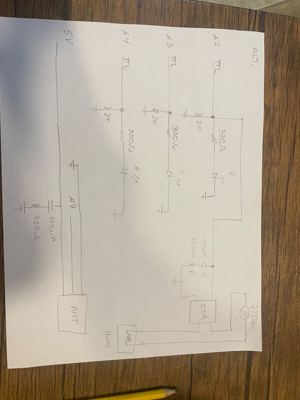
New circ
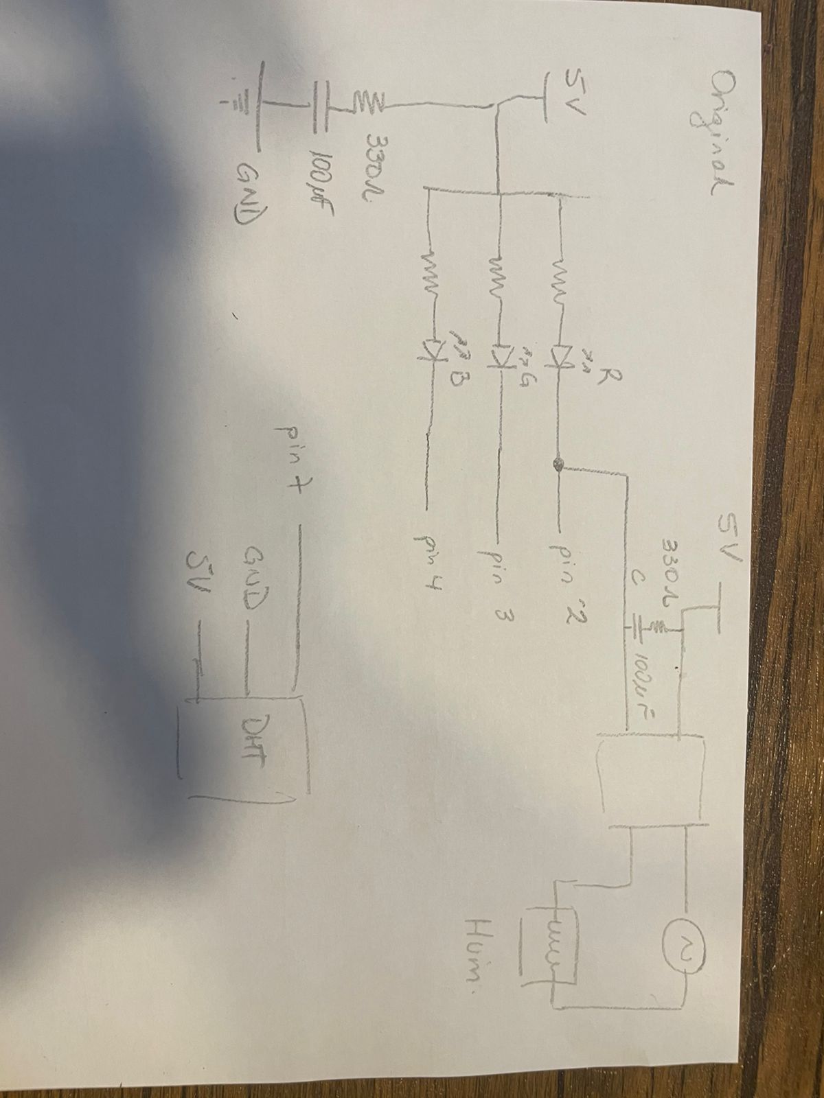
Original circ