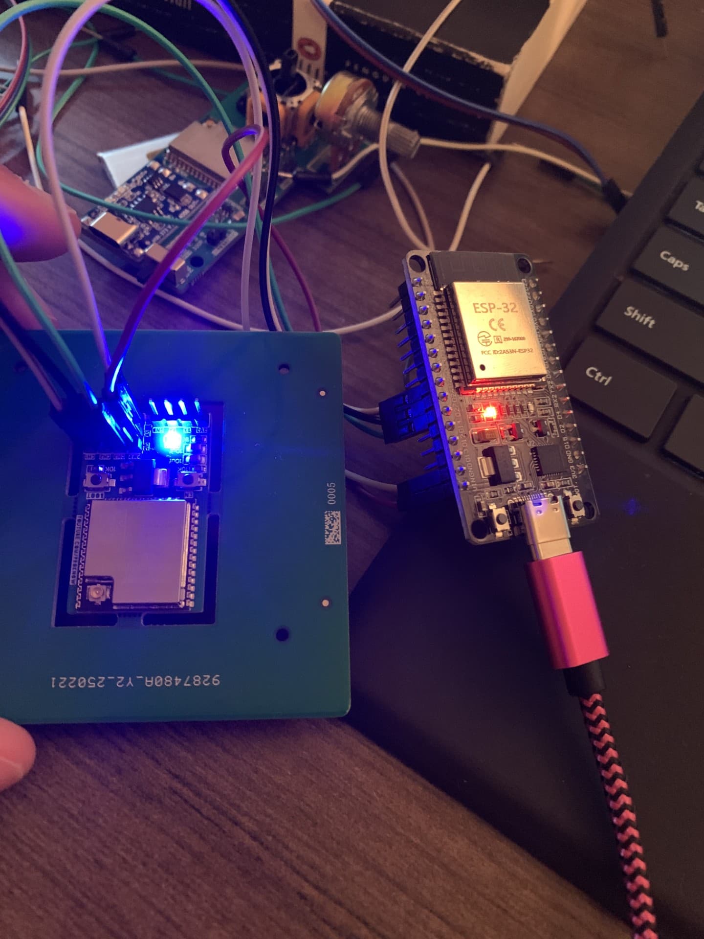
Hey guys! I am currently having a bit of an issue with my esp32. Its hard to explain in words exactly what is happening so I am going to show an image.
What I am trying to do in the picture is upload code from the esp32(non Pcb) to the Esp32(PCB). I don't know if it exactly possible but I want to know what you guys say before coming to any conclusions. Preferebly I would love to be able to upload code to the other ESP32(PCB).
Ps.
I am only getting the Mac Address from the esp32(non PCB)
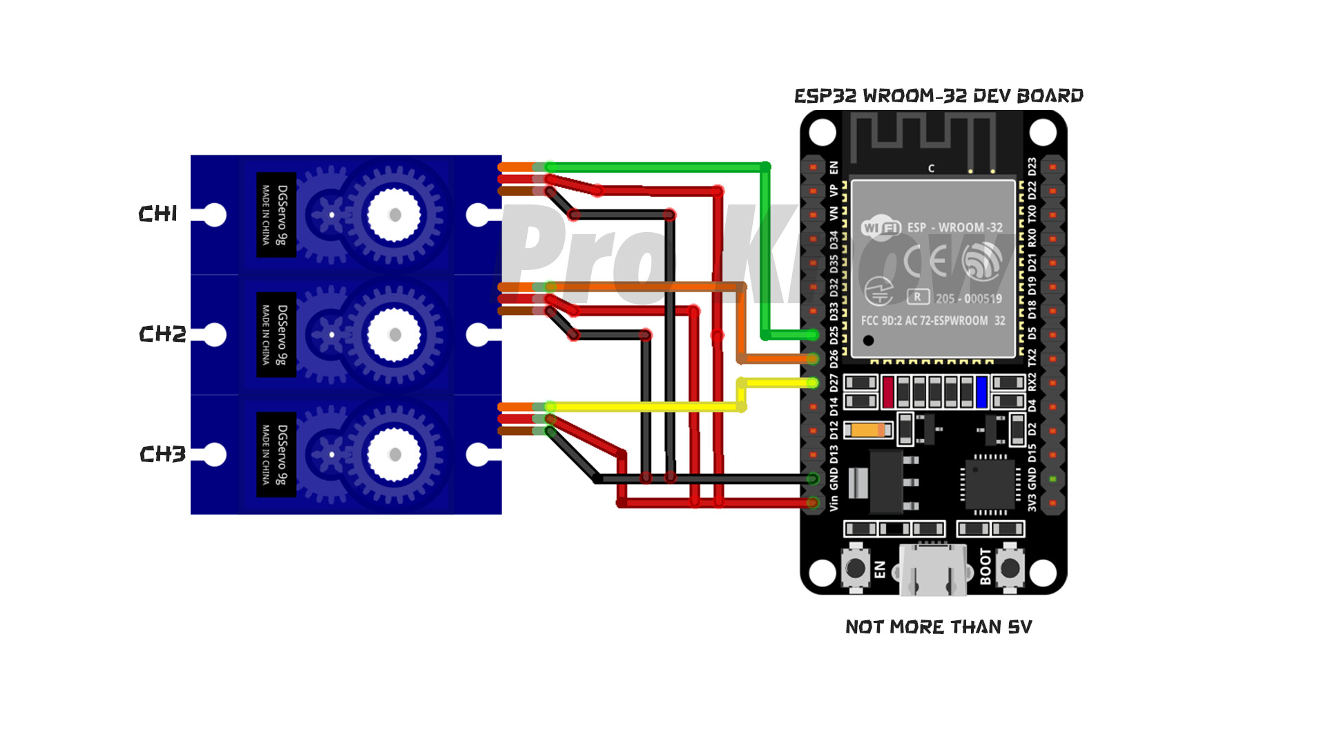
I am afraid that you are going to have to explain it in words as well as posting a schematic showing how components of your project are connected and powered and any sketches that are running
I am afraid that was a waste of time as it is impossible to see what is connected to what
Another piece of context.
The Esp32(Non PCB) works fine and gives me the Mac Address. I just want to have extra range and be able to have everything on the pcb for convenience.
Why has your so called "schematic" only got one ESP32 in it along with what appear to be 3 servos ? What has that got to do with what you say you are trying to do ?
As I said before UKHeliBob, I wanted to try working more range from the esp32 which is why I have the pcb. The pcb will be in charge of each Servo since I configured it to be so. I wanted to upgrade the project hence why there is only one esp32. It was originally only for the original esp32. Maybe that clears it up a bit more? If not then ask more questions so that I can help you to help me out. Thanks
Hi @lolfast800. Please describe the electrical connections you have made between the "non Pcb" board the "PCB" board. You can do that by providing a schematic (but we need the schematic of those connections, not the irrelevant one with the servos that you already provided) of, or a per-pin list of the connections between the boards.
Please provide a detailed description of what you mean by this.
Do you mean that you are only using the "non Pcb" board as a USB to serial adapter between the computer and the "PCB" board, clicking the "Upload" button in Arduino IDE to upload the sketch from the computer to the "PCB" board?
Or do you truly mean that you want the "non Pcb" board to transfer a program from is memory to the "PCB" board?