ESP32 Dev Module rebooting while using MX1508

Hi, hope you all are fine

I'm working on a project using:

  • ESP32 DEVKIT V1 (ESP32 Dev Module in Arduino IDE)
  • 2x MX1508 DC motor drivers
  • MG996R servo
  • LM7805 voltage regulator
  • 2S 18650 battery (7.4V 1200mAh)

When i finished coding and wiring, for some days of testing it worked fine (driving motors, servo doing its job), but suddenly, one of the MX1508 just burned and it take out the esp32 too, i changed the wiring, checked for short circuits, and nothing, i tested it again with replacements but now when its on, if doing nothing the esp32 is fine, but soon as i get the servo or the mx1508 running, the esp32 now reboots and any control is lost.

Here is the schematic:

Notes:

  • GND_POINT is where i soldered every gnd of the components
  • I didnt include the wirings for the GPIOs as i dont consider important for the problem
  • In the schematic there are two DRV8833PW, those are the representations for the MX1508, as i cannot find any existing symbols

Am i doing something wrong? please any help would be appreciated.

Thanks!

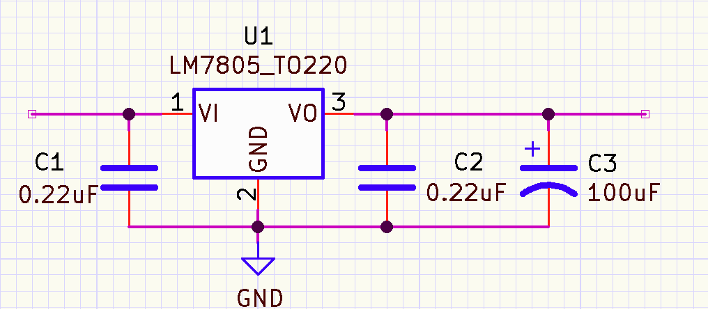
Missing input and output capacitors for the LM7805
The MX1508 does not have GND. Do you mean -VE?
The 3.3V GPIOs of the ESP can't drive the MX1508 inputs.

And LM7805 is likely not able to supply current for that servo and rest of the setup.
Servo alone has stall current >2A.

Are you sure it's a MX1508 IC and not a TC1508?

Yes, i mean -VE, and you’re right is an TC1508
Lol, that has me wondering why in another projects it works with MX1508 inputs, anyway i am looking for other options of dc drivers, maybe DRV8833

The TC and MX are different. The TC will work with 3.3V control signals, the MX may or may not. The input threshold for the MX is 3.0V which iv very close to 3.3V and will be prone to noise and voltage drops.

In any case you need the caps on the regulator.

I am currently looking for the caps, good point

Oh alright, so thats why it has worked in the past, yeah i only have TC

Will it work with a buck converter? i also found a lm2596 but is 2a max

The LM7805 can handle peak output currents of 2.4A, so it should not be a problem.

Thanks a lot! im going to get the caps and will test it out, i’ll update the results here

Yes, but for best support here you should present your complete circuit. How are the motors powered?

Hi, @carodecobrar
Welcome to the forum.

Can you post some images of your project?
So we can see your component layout.

Tom.... :smiley: :+1: :coffee: :australia:

I recommend this:
The 0.22uF caps are ceramic, the 100uF is electrolytic

sorry i didnt put the dc motors in the schematic, here it is:

currently the TC1508 takes the 7.4v and with that drives the dc motors

Well that is a problem since the max voltage for the TC is 5V, it's higher for the MX.

That has VIN voltage range of 4.5-12V. You could power it directly from battery, so if LM7805 trips under heavy load, it doesn't boot your board.
Also, LM might misbehave if your battery is on low charge or under heavy load and the voltage goes below 7V.

But i have another circuit which has two TC powered by 7.4v, and never has burned or rebooted the esp32

This is the module:

I did that when i was starting to make the dc motors work with esp32, but i guess the current “load” was too much and the esp got reset, so thats why i put the lm7805

They don't necessarily fail right away.

The cicuit operation is unpredictable without the caps on the requlator.

2 Likes