ESP32 - Readings with Wind Direction sensor via RS485

Hello community,

I am building a weather station and bought a RS485 Modbus wind direction sensor. I am new to RS485, and have been diving a lot into modbus coding, registers, addresses and transmitter/reciever roles, guessing I could get to solve this problem, but here I am. Couldn't sort it out yet and that is the reason why I ask you for a bit of help (I feel I'm close!).

https://es.aliexpress.com/item/1005004770322638.html?spm=a2g0o.order_list.order_list_main.106.21ef194d8VQ2Wt&gatewayAdapt=glo2esp

https://es.aliexpress.com/item/32427910931.html?spm=a2g0o.order_list.order_list_main.304.21ef194d8VQ2Wt&gatewayAdapt=glo2esp

I have been deeply looking for very very similar posts, and even tried their codes (some of the had the same sensor settings in fact, same connection and RS module), but got no successful results.

Y have an ESP32 Devkit v4, MAX485 with 5V supply and the wind direction sensor offering A and B RS485 terminals connected to MAX485_

  • DE and RE connected together for easier control of transmitter/receiver.
  • DI to GPIO16 named in the code as RX_PIN
  • R0 to GPIO 17 named in the code as TX_PIN
    Sensors ground is not connected to ESP32/MAX485 ground, as the source is independent (one comes from a 12V battery and the other from the computer USB; final prototype has same source with a DC/DC controller but for coding and testing purposes I am doing it that way in order to check serial communication with the computer).

I tested the sensor connected via CH340 USB to the computer and get correct hexagesimal results with the drives given by the sensor's supplier, but when it comes to coding the ESP32 I am not able to get sensor readings.

#include <SoftwareSerial.h>

#define RX_PIN 16
#define TX_PIN 17
#define DERE_PIN 5

SoftwareSerial modbusSerial(RX_PIN, TX_PIN);

const byte request[] = {0x01, 0x03,0x00 ,0x00, 0x00 ,0x02, 0xC4, 0x0B};
byte values[11];
const uint32_t TIMEOUT = 500UL;

void setup() {
  pinMode(DERE_PIN, OUTPUT);
  digitalWrite(DERE_PIN, LOW);
  modbusSerial.begin(4800, SWSERIAL_8N1);
  Serial.begin(115200);
}

void loop() {
  
  byte val1;

  Serial.println("Vane: ");
  val1 = vane();
  delay(250);
  Serial.println(val1);
  Serial.println(" degrees");
  Serial.println(sizeof(request));
  delay(5000);
}

byte vane() {
    uint32_t startTime = 0;
    uint8_t  byteCount = 0;

    digitalWrite(DERE_PIN, HIGH);
    delay(10);

    if(modbusSerial.write(request,sizeof(request))==8){
      digitalWrite(DERE_PIN, LOW);
      for(byte i=0;i<7;i++){
        Serial.print(modbusSerial.read(),HEX);
        values[i] = modbusSerial.read();
        Serial.print(values[i],HEX);
      }
      Serial.println();
    }

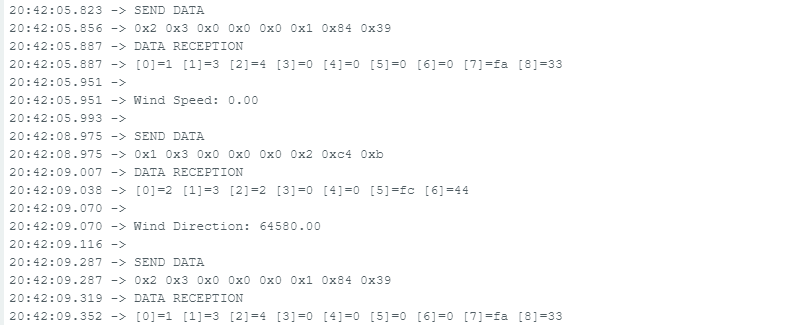
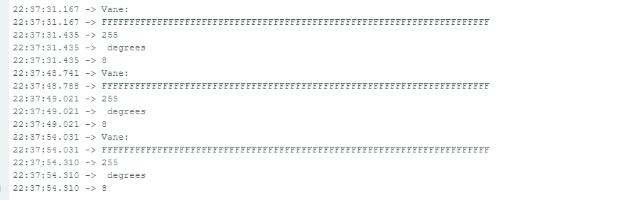
This is what I get from serial:

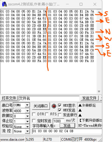
And this is what I get from the USB RS485 adapter connected to PC.

Sorry but executable given by provider is in chinese and couldn't manage to translate it. I just followed their instructions (uploaded below).
Wind Vane instructions-RS485_EN.pdf (1,8 MB)

I would very appreciate your help. I feel stuck on this taking me a lot of time... Please help!!
Thank you in advance,

Gorka

the first thing is to check RS485 communication
get a USB-485 dongle for a PC - I use a FTDI USB-RS485-WE-1800-BT but low cost dongles are available on EBAY
Connect the USB-RS485 dongle to the ESP32/RS485module and test using a simple program such as

// ESP32 Serial1 to RS485 bus

#define RS485Serial Serial1  // hardware serial port on ESP32

// RS485 VCC ESP32 to to 3.3V
#define RXD2 16  //  ESP32 Serial1 Receive  pin 16 to RS485 RO/RXD
#define TXD2 17  //  ESP32 Serial1 Transmit pin 17 to RS485 DI/TXD

// RS485 DE and RE to ESP32 pins 18 and 19
#define DE 18  //RS485 Direction control pin
#define RE 19  //RS485 Direction control pin

#define RS485Transmit HIGH
#define RS485Receive LOW

void setup() {
  Serial.begin(115200);  
  delay(1000);
  Serial.println("ESP32 connect to RS485 bus - enter/receive text");
  pinMode(DE, OUTPUT);
  pinMode(RE, OUTPUT);
  digitalWrite(DE, RS485Receive);                     // Disable RS485 Transmit
  digitalWrite(RE, RS485Receive);                     // Disable RS485 Transmit
  RS485Serial.begin(115200, SERIAL_8N1, RXD2, TXD2);  // set the RS485 data rate
}

// loop sending data to RS485 and receiving data
void loop() {
  if (Serial.available()) {            // Arduino Serial data avaliable?
    digitalWrite(DE, RS485Transmit);   // Enable RS485 Transmit
    digitalWrite(RE, RS485Transmit);   // Enable RS485 Transmit
    RS485Serial.write(Serial.read());  // Send byte to Remote Arduino
    RS485Serial.flush();               // wait for byte to be transmitted
    digitalWrite(DE, RS485Receive);    // Disable RS485 Transmit
    digitalWrite(RE, RS485Receive);    // Disable RS485 Transmit
  }

  if (RS485Serial.available())         // RS485 serial data available?
    Serial.write(RS485Serial.read());  // read character and display it
}

running the code the ESP32 displays


test1 from pc
test 2 from pc 1234567890
test3 from pc abcdef

running teraterm terminal emulator (local echo on) on a PC displays

test1 from ESP32
test2 1234567890
test3 abcdefghijk
test1 from pc
test 2 from pc 1234567890
test3 from pc abcdef
test4 from ESP32 98765432

photo of test

once RS485 communication is working connect the RS485 device

  1. have web search for PC modbus software - see if the PC can communicate with the device
  2. run the ESP32 modbus software

You have these the wrong way round. DI goes to your Tx pin and RO goes to the Rx pin.

Also note that the MAX485 is a 5V device. You should level shift the RO signal down to 3.3V to avoid damaging your ESP32.

And +1 for a USB-RS485 dongle. It will help with diagnosing RS485 Comms if you get stuck.

Mark and Horace, thanks for your quick reply.

Really good idea to test RS485 Modbus communication between ESP32 and PC first. I got sensor communication successful between PC and sensor but, not between PC and ESP32. I have been trying to replicate and follow your steps (with your code) and many others showed in many places about Modbus RTU; tried with TeraTerm, Putty, ModbusPoll but no success. I am a bit lost as I don't know exactly how to attack this point.

I was expecting to send a test request to the ESP32 from the PC in order to get your serial results, but don't know where to start from. How do I know what address should I knock in order to get answer? I understand that the ESP32 is waiting for an answer, so the problem is that I somehow don't get the query right. I would very appreciate if you'd know somewhere reliable to dive into, as all the tutorials and pages I've looked into were not showing "how" to do it - RTU Modbus communication between ESP32 slave and PC master.

And thanks for the comment about DI and R0 pins. I put them correctly but wind sensor (and neither PC communication) was not successful, so I guess is something about libraries/programming?

I understand RS485 Modbus protocol but every try I make in different ways results unsuccessful. I think my concepts are OK but cannot apply them correctly.
I would really appreciate some more detailed clues about which bibliography could I dive into or references... Please!

not sure what you are attempting to do
if your sensor communicates with the PC OK what is the function of the ESP32?

This demonstrates a common error seen many times with RS485 serial comms in this forum and on the web in general - especially when authors present their apparently working code for the NPK soil sensor (another Modbus sensor).

The issue here is that once the request for the data has been sent to the sensor and the RS485 transceiver has been put back into receive mode (ignoring any flush command as in this case I don't think it's needed with a software serial port), the code assumes that the reply from the sensor is instantly available and goes into a loop reading the expected number of bytes.

This generally results in the user getting a byte array filled with 0xFF. The 0xFF is there because the serial port is reporting back -1, which is its way of saying that no data was available because the sensor hasn't responded yet.

Thank you both for your answers.
Answering to Horace: the point in communicating the ESP32 with the sensor is because I want to put an outside weather station logging data that won't be connected to the computer. I tested the sensor and this OK gave me the clue that was absolutely a coding error. I consider a good idea to try to test the ESP32 communication with the PC in order to learn and go deeper in how this protocol works, but haven't got any success yet; I think I will get back to the sensor directly as I find coding easier.

And thank you Mark for your clue. I have tried 3 libraries: HardwareSerial, SoftwareSerial and ModbusMaster, and in every of them changed the directional controls to receive mode. I will try to implement what you say and tell you how it goes.

There is something wrong here that I am not doing/considering but it shouldn't be difficult. I wish to fix it soon and I'll let you know how I've done it.

Thanks!

you could

  1. the ESP32 collects data from the weather station using Modbus (save it to SD card?)
  2. when required upload data to PC using WiFi

Hello!

Sorry for the delay in the answer; I have been advancing with the sensors measurements and Modbus RTU settings, and finally got the sensors readings OK. I got it without any library, just with Serial2 UART pins in the ESP32. I come back to you hoping you could help me. I have very little left!

I managed to buy a new RS485 TTL converter operating in 3,3V instead the 5V I had (as markd833 mentioned), and got to read the sensors independently with the ESP32 and Serial2, without any additional library. I can understand the code and even if I managed to change sensors settings to change ID number, and Baud rate (both at 9600), getting a code that could read each one independently, when putting them together I got stuck.

The thing is that Vane's answer to my query comes as the Anemometer's response and the Anemometers response comes with the Vane's query. This is strange as the ID's of both are different, specifically changed for so (Vane ID=1, Anemo ID=2). They are both connected in parallel to the same A - B wiring, let me show you a scheme.

I tried inserting delays in different places but no success. Also added a Timeout of 1000ms but stays the same. Is like if the vane answered to anemometer's query and viceversa. The strange thing is that if I disable anemo or vane's code lines, the other sensor measures correctly and response times are correct; 0.2s. What do you think can it be? Something related to the buffer?

Let me share with you my code.

#define RXD2 16
#define TXD2 17

byte ByteArrayVane[8];
int ByteDataVane[2];
byte ByteArrayAnemo[8];
int ByteDataAnemo[2];

void setup() {

  Serial.begin(9600);
  Serial2.begin(9600, SERIAL_8N1, RXD2, TXD2);
  Serial2.setTimeout(1000);
}

void loop() {

 delay(200);
       
 byte msgVane[] = {0x01,0x03,0x00,0x00,0x00,0x02,0xC4,0x0B}; // ID = 1 Vane

 int i;
 int len=8; 

Serial.println("ENVIO DATOS  -  SEND DATA");
for(i = 0 ; i < len ; i++){
      Serial2.write(msgVane[i]); 
        Serial.print("0x");
        Serial.print(String(msgVane[i], HEX));
        Serial.print(" ");   
 }

int a = 0;
  while(Serial2.available()) {
    ByteArrayVane[a] = Serial2.read();
    a++;
  }

//HERE GOES THE PRINTING OF VANE RECEIVING

ByteDataVane[1] = ByteArrayVane[5] * 256 + ByteArrayVane[6];

float wind_direction;
wind_direction = ByteDataVane[1];
Serial.println(wind_direction);

delay(1000);
       
byte msgAnemo[] = {0x02,0x03,0x00,0x00,0x00,0x01,0x84,0x39}; // ID = 2 Anemo

len=8; 

Serial.println("DATA QUERY");
for(i = 0 ; i < len ; i++){
      Serial2.write(msgAnemo[i]); 
        Serial.print("0x");
        Serial.print(String(msgAnemo[i], HEX));
        Serial.print(" ");   
 }
 len = 0;
 Serial.println();

a = 0;
  while(Serial2.available()) {
    ByteArrayAnemo[a] = Serial2.read();
    a++;
  }

//HERE GOES THE PRINTING OF ANEMO RECEIVING

ByteDataAnemo[0] = ByteArrayAnemo[3]*256  + ByteArrayAnemo[4];

float wind_speed;
wind_speed = ByteDataAnemo[0]*0.10;
Serial.println(wind_speed, 2);

delay(2000);

}

This is the error I'm getting.

I hope you guys or someone could help me with ordering my readings.
Thank you in advance.

you transmit using Serial2 then immediately call Serial2.available() - it is possible nothing has been received in that time - put a short delay between the transmit and receive? delay(20) ?

I got it finally.

It resulted that somehow, the vane sensor was the one giving problems. Inserted 20ms delay between query and Serial2 reading, and something curious happened: I changed the reading order to first anemometer and then vane and it resulted.

Now I can read both sensors with 1,3s delay between readings. I wish it could be less, with a 1Hz frequency but is OK now!

By the way, the code printed above with this delay and order modifications is the one working :slight_smile:
Thank you for the help!

hello
I bought RS 485 sensors like yours to make a weather station but I couldn't get the drivers from the seller.
Is it possible to share these drivers??
Thank you

Hello!

If you are programming on the ESP32 you don't need any driver apart from the default UART ports that the ESP has, or at least that is what I did.
Check that you are supplying the voltage needed by the transmitter and test Rx and Tx signals with a USB-to-RS485 adapter into the computer with a simulator software.
If you want to use a 5V transmitter check that the Rx and Tx signals have the volgate admitted by the ESP32.

Hope to have helped you!!
Good luck

Hello

Thanks for the reply.

I will follow your advice

Thank you very much.

This topic was automatically closed 180 days after the last reply. New replies are no longer allowed.