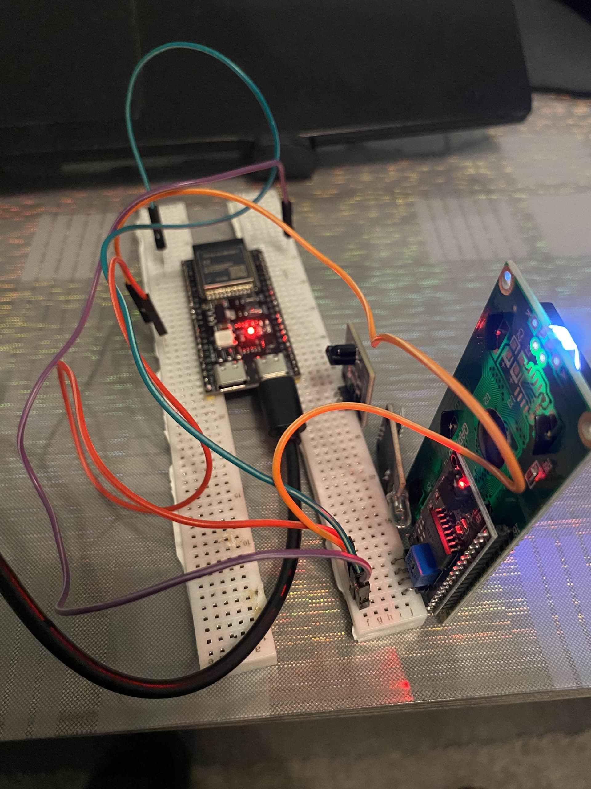
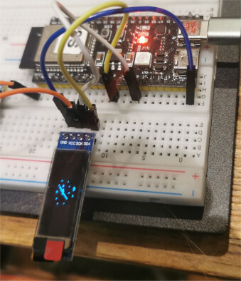
using a ESP32-S3-DevKitC-1 connected a SSD1306 display to I2C
running the I2Cscanner code from post 1 I get
I2C Scanner
Scanning...
I2C device found at address 0x3C  !
done
running the following ClockDemo code
// library https://github.com/LilyGO/ESP32-OLED0.96-ssd1306

/**
 * The MIT License (MIT)
 *
 * Copyright (c) 2016 by Daniel Eichhorn
 * Copyright (c) 2016 by Fabrice Weinberg
 *
 * Permission is hereby granted, free of charge, to any person obtaining a copy
 * of this software and associated documentation files (the "Software"), to deal
 * in the Software without restriction, including without limitation the rights
 * to use, copy, modify, merge, publish, distribute, sublicense, and/or sell
 * copies of the Software, and to permit persons to whom the Software is
 * furnished to do so, subject to the following conditions:
 *
 * The above copyright notice and this permission notice shall be included in all
 * copies or substantial portions of the Software.
 *
 * THE SOFTWARE IS PROVIDED "AS IS", WITHOUT WARRANTY OF ANY KIND, EXPRESS OR
 * IMPLIED, INCLUDING BUT NOT LIMITED TO THE WARRANTIES OF MERCHANTABILITY,
 * FITNESS FOR A PARTICULAR PURPOSE AND NONINFRINGEMENT. IN NO EVENT SHALL THE
 * AUTHORS OR COPYRIGHT HOLDERS BE LIABLE FOR ANY CLAIM, DAMAGES OR OTHER
 * LIABILITY, WHETHER IN AN ACTION OF CONTRACT, TORT OR OTHERWISE, ARISING FROM,
 * OUT OF OR IN CONNECTION WITH THE SOFTWARE OR THE USE OR OTHER DEALINGS IN THE
 * SOFTWARE.
 *
 */

#include <TimeLib.h>

// Include the correct display library
// For a connection via I2C using Wire include
#include <Wire.h>  // Only needed for Arduino 1.6.5 and earlier
#include "SSD1306.h" // alias for `#include "SSD1306Wire.h"`
// or #include "SH1106.h" alis for `#include "SH1106Wire.h"`
// For a connection via I2C using brzo_i2c (must be installed) include
// #include <brzo_i2c.h> // Only needed for Arduino 1.6.5 and earlier
// #include "SSD1306Brzo.h"
// #include "SH1106Brzo.h"
// For a connection via SPI include
// #include <SPI.h> // Only needed for Arduino 1.6.5 and earlier
// #include "SSD1306Spi.h"
// #include "SH1106SPi.h"

// Include the UI lib
#include "OLEDDisplayUi.h"

// Include custom images
#include "images.h"

// Use the corresponding display class:

// Initialize the OLED display using SPI
// D5 -> CLK
// D7 -> MOSI (DOUT)
// D0 -> RES
// D2 -> DC
// D8 -> CS
// SSD1306Spi        display(D0, D2, D8);
// or
// SH1106Spi         display(D0, D2);

// Initialize the OLED display using brzo_i2c
// D3 -> SDA
// D5 -> SCL
// SSD1306Brzo display(0x3c, D3, D5);
// or
// SH1106Brzo  display(0x3c, D3, D5);

// Initialize the OLED display using Wire library
//SSD1306  display(0x3c,5, 4);//, D1, D2);
SSD1306  display(0x3c,8,9);//, D1, D2);
// SH1106 display(0x3c, D3, D5);

OLEDDisplayUi ui ( &display );

int screenW = 128;
int screenH = 64;
int clockCenterX = screenW/2;
int clockCenterY = ((screenH-16)/2)+16;   // top yellow part is 16 px height
int clockRadius = 23;

// utility function for digital clock display: prints leading 0
String twoDigits(int digits){
  if(digits < 10) {
    String i = '0'+String(digits);
    return i;
  }
  else {
    return String(digits);
  }
}

void clockOverlay(OLEDDisplay *display, OLEDDisplayUiState* state) {

}

void analogClockFrame(OLEDDisplay *display, OLEDDisplayUiState* state, int16_t x, int16_t y) {
//  ui.disableIndicator();

  // Draw the clock face
//  display->drawCircle(clockCenterX + x, clockCenterY + y, clockRadius);
  display->drawCircle(clockCenterX + x, clockCenterY + y, 2);
  //
  //hour ticks
  for( int z=0; z < 360;z= z + 30 ){
  //Begin at 0° and stop at 360°
    float angle = z ;
    angle = ( angle / 57.29577951 ) ; //Convert degrees to radians
    int x2 = ( clockCenterX + ( sin(angle) * clockRadius ) );
    int y2 = ( clockCenterY - ( cos(angle) * clockRadius ) );
    int x3 = ( clockCenterX + ( sin(angle) * ( clockRadius - ( clockRadius / 8 ) ) ) );
    int y3 = ( clockCenterY - ( cos(angle) * ( clockRadius - ( clockRadius / 8 ) ) ) );
    display->drawLine( x2 + x , y2 + y , x3 + x , y3 + y);
  }

  // display second hand
  float angle = second() * 6 ;
  angle = ( angle / 57.29577951 ) ; //Convert degrees to radians
  int x3 = ( clockCenterX + ( sin(angle) * ( clockRadius - ( clockRadius / 5 ) ) ) );
  int y3 = ( clockCenterY - ( cos(angle) * ( clockRadius - ( clockRadius / 5 ) ) ) );
  display->drawLine( clockCenterX + x , clockCenterY + y , x3 + x , y3 + y);
  //
  // display minute hand
  angle = minute() * 6 ;
  angle = ( angle / 57.29577951 ) ; //Convert degrees to radians
  x3 = ( clockCenterX + ( sin(angle) * ( clockRadius - ( clockRadius / 4 ) ) ) );
  y3 = ( clockCenterY - ( cos(angle) * ( clockRadius - ( clockRadius / 4 ) ) ) );
  display->drawLine( clockCenterX + x , clockCenterY + y , x3 + x , y3 + y);
  //
  // display hour hand
  angle = hour() * 30 + int( ( minute() / 12 ) * 6 )   ;
  angle = ( angle / 57.29577951 ) ; //Convert degrees to radians
  x3 = ( clockCenterX + ( sin(angle) * ( clockRadius - ( clockRadius / 2 ) ) ) );
  y3 = ( clockCenterY - ( cos(angle) * ( clockRadius - ( clockRadius / 2 ) ) ) );
  display->drawLine( clockCenterX + x , clockCenterY + y , x3 + x , y3 + y);
}

void digitalClockFrame(OLEDDisplay *display, OLEDDisplayUiState* state, int16_t x, int16_t y) {
  String timenow = String(hour())+":"+twoDigits(minute())+":"+twoDigits(second());
  display->setTextAlignment(TEXT_ALIGN_CENTER);
  display->setFont(ArialMT_Plain_24);
  display->drawString(clockCenterX + x , clockCenterY + y, timenow );
}

// This array keeps function pointers to all frames
// frames are the single views that slide in
FrameCallback frames[] = { analogClockFrame, digitalClockFrame };

// how many frames are there?
int frameCount = 2;

// Overlays are statically drawn on top of a frame eg. a clock
OverlayCallback overlays[] = { clockOverlay };
int overlaysCount = 1;

void setup() {
  Serial.begin(115200);
  Serial.println();

	// The ESP is capable of rendering 60fps in 80Mhz mode
	// but that won't give you much time for anything else
	// run it in 160Mhz mode or just set it to 30 fps
  ui.setTargetFPS(60);

	// Customize the active and inactive symbol
  ui.setActiveSymbol((const uint8_t*)activeSymbol);
  ui.setInactiveSymbol((const uint8_t*)inactiveSymbol);

  // You can change this to
  // TOP, LEFT, BOTTOM, RIGHT
  ui.setIndicatorPosition(TOP);

  // Defines where the first frame is located in the bar.
  ui.setIndicatorDirection(LEFT_RIGHT);

  // You can change the transition that is used
  // SLIDE_LEFT, SLIDE_RIGHT, SLIDE_UP, SLIDE_DOWN
  ui.setFrameAnimation(SLIDE_LEFT);

  // Add frames
  ui.setFrames(frames, frameCount);

  // Add overlays
  ui.setOverlays(overlays, overlaysCount);

  // Initialising the UI will init the display too.
  ui.init();

  display.flipScreenVertically();

  unsigned long secsSinceStart = millis();
  // Unix time starts on Jan 1 1970. In seconds, that's 2208988800:
  const unsigned long seventyYears = 2208988800UL;
  // subtract seventy years:
  unsigned long epoch = secsSinceStart - seventyYears * SECS_PER_HOUR;
  setTime(epoch);

}


void loop() {
  int remainingTimeBudget = ui.update();

  if (remainingTimeBudget > 0) {
    // You can do some work here
    // Don't do stuff if you are below your
    // time budget.
    delay(remainingTimeBudget);

  }


}
with images.h file (in same directory as above .ino file)
const char activeSymbol[] PROGMEM = {
    B00000000,
    B00000000,
    B00011000,
    B00100100,
    B01000010,
    B01000010,
    B00100100,
    B00011000
};

const char inactiveSymbol[] PROGMEM = {
    B00000000,
    B00000000,
    B00000000,
    B00000000,
    B00011000,
    B00011000,
    B00000000,
    B00000000
};
displays