ESP32 writing weird symbols in console while driving PWM

Hi,

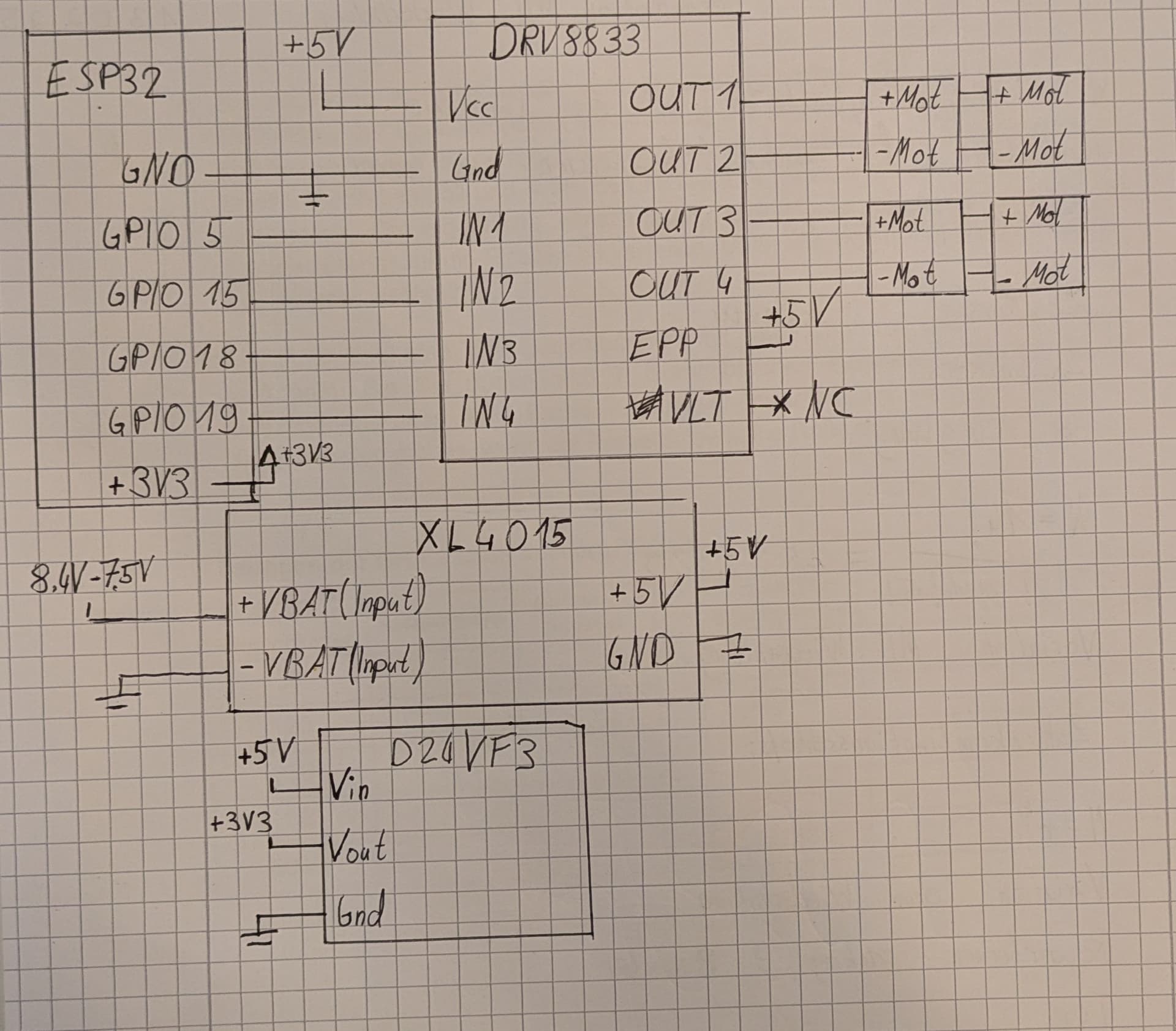
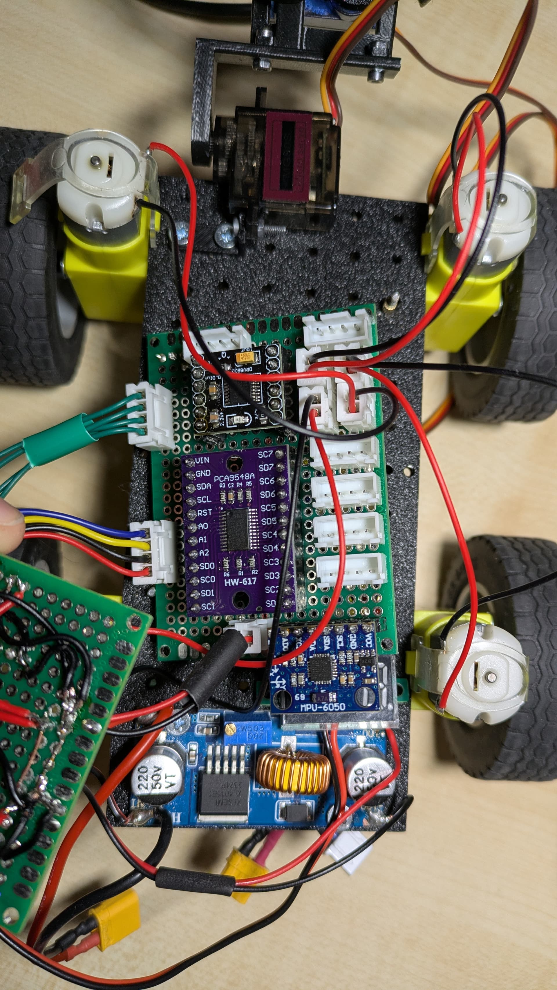
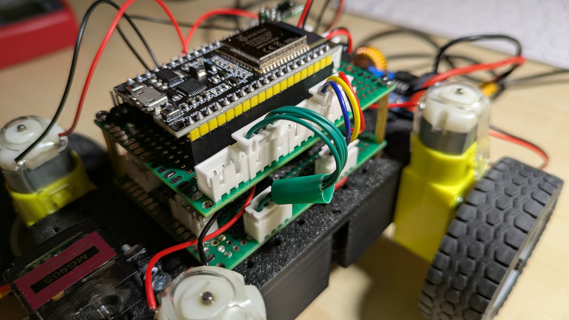
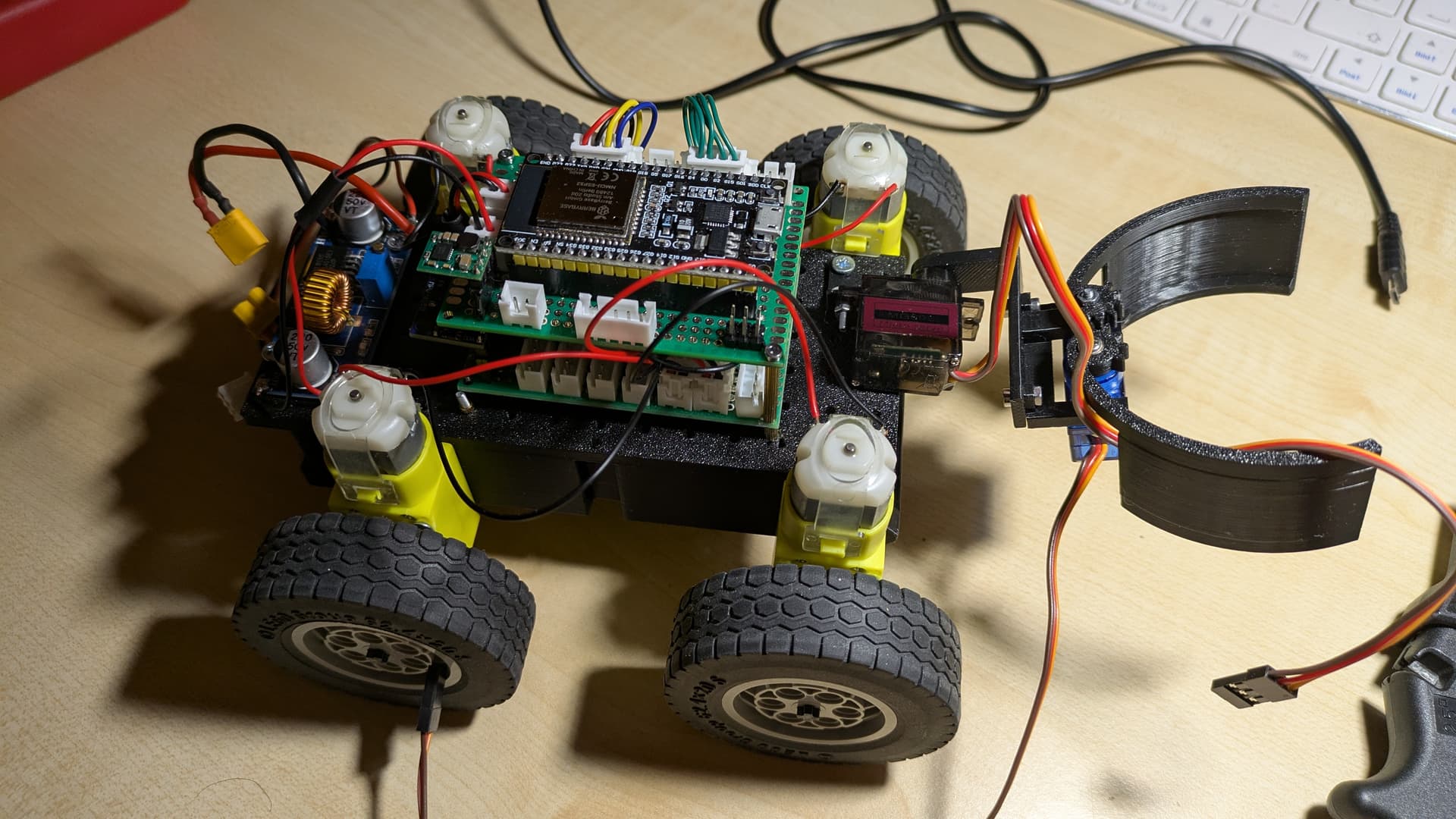
I'm currently working on a 4 wheeled robot, with 2 Servos for a gripper and 4 geared TT Motors to drive. I use a ESP32 NodeMCU to control everything. To drive the Motors, I use a DRV8833 dual H bridge, two Motors(on the same side) are connected to each other, because they are always driving the same speed and direction. The entire system is powered by a 2S Lipo(8.4v- 7.5v) that's lowered to 5V using a Step Down Converter(with a max current of 5A). These 5V are converted to 3.3V using an LDO and fed to the ESP32. The DRV8833 and therefore the motors are getting 5V. My problem is, that seemingly randomly(but often when I run the sides in opposite direction to rotate like a tank) the ESP32 "crashes" and starts spitting out random symbols in the console(my baud Rate is set to 115200). This happens even when not using the Servos or any other peripheral. Here is my code:

void setup() {
  Serial.begin(115200);
}

void loop() {
  move(0, 0, 100);
  move(175, 175, 2000);
  move(-185, 185, 1700);
  move(-255, -255, 500);
  move(175, 175, 500);
}

void move(int _motorA, int _motorB, int _duration) {
  
  if(_motorA > 0) {
    pinMode(5, OUTPUT);
    digitalWrite(5, LOW);
    ledcAttachChannel(15, 5000, 8, 7);
    ledcWrite(15, abs(_motorA));
  }

  else if(_motorA <= 0) {
    pinMode(15, OUTPUT);
    digitalWrite(15, LOW);
    ledcAttachChannel(5, 5000, 8, 7);
    ledcWrite(5, abs(_motorA));
  }
  
  if(_motorB > 0) {
    pinMode(18, OUTPUT);
    digitalWrite(18, LOW);
    ledcAttachChannel(19, 5000, 8, 8);
    ledcWrite(19, abs(_motorB));
  }

  else if(_motorB <= 0) {
    pinMode(19, OUTPUT);
    digitalWrite(19, LOW);
    ledcAttachChannel(18, 5000, 8, 8);
    ledcWrite(18, abs(_motorB));
  }
  
  delay(_duration);
}

and this is my console(I have the log mode set to verbose):

[ 31479][V][esp32-hal-periman.c:160] perimanSetPinBus(): Pin 15 successfully set to type GPIO (1) with bus 0x10
[ 31489][V][esp32-hal-periman.c:235] perimanSetBusDeinit(): Deinit function for type LEDC (12) successfully set to 0x400d2670
[ 31500][V][esp32-hal-periman.c:160] perimanSetPinBus(): Pin 5 successfully set to type INIT (0) with bus 0x0
[ 31510][V][esp32-hal-periman.c:160] perimanSetPinBus(): Pin 5 successfully set to type LEDC (12) with bus 0x3ffb8b10
[ 31520][I][esp32-hal-ledc.c:166] ledcAttachChannel(): LEDC attached to pin 5 (channel 7, resolution 8)
[ 31530][V][esp32-hal-periman.c:235] perimanSetBusDeinit(): Deinit function for type LEDC (12) successfully set to 0x400d2670
[ 31541][E][esp32-hal-ledc.c:111] ledcAttachChannel(): Pin 19 is already attached to LEDC (channel 8, resolution 8)
[ 33251][V][esp32-hal-periman.c:235] perimanSetBusDeinit(): Deinit function for type LEDC (12) successfully set to 0x400d2670
[ 33262][E][esp32-hal-ledc.c:111] ledcAttachChannel(): Pin 5 is already attached to LEDC (channel 7, resolution 8)
[ 33272][V][esp32-hal-periman.c:235] perimanSetBusDeinit(): Deinit function for type GPIO (1) successfully set to 0x400f5344
[ 33283][V][esp32-hal-periman.c:160] perimanSetPinBus(): Pin 19 successfully set to type INIT (0) with bus 0x0
[ 33293][V][esp32-hal-periman.c:160] perimanSetPinBus(): Pin 19 successfully set to type GPIO (1) with bus 0x14
[ 33302][V][esp32-hal-periman.c:235] perimanSetBusDeinit(): Deinit function for type LEDC (12) successfully set to 0x400d2670
[ 33313][V][esp32-hal-periman.c:160] perimanSetPinBus(): Pin 18 successfully set to type INIT (0) with bus 0x0
[ 33323][V][esp32-hal-periman.c:160] perimanSetPinBus(): Pin 18 successfully set to type LEDC (12) with bus 0x3ffb8b48
[ 33334][I][esp32-hal-ledc.c:166] ledcAttachChannel(): LEDC attached to pin 18 (channel 8, resolution 8)
1�|mlh%a �tR(�nL(�tR0n#��bInxnh �|�[p*%fa#N8|?�X,,�tP!tP'tP*ttP7n�X,l �ubn@)~zP5 �r-%*va. �r-!l-,*van �A,nzAl�*n �r-,%.�alo 1�|m�lh%a �tV1��Sb3L(�tRdnnbbnxnh �|'[p*%faN8|?�X,,tP!t�P'tP*ttP7n�X,l ��bn@)~zP5 �r-%*va. �r-!l-,*van �A,nzAl5*n �r-,�.�alo 1�|mlh%a �tV17�bL(�tRdn�nbbnxnh �|'[p*%fa#N8|?�X,,tP!tP'tP*ttP�n�X,l �ubn@)~zP5 �r-%*va. �r-!l-,*vanB!~,nzAl5*n �r-,%.�alo� 1�|mlh%a �tV17�b3L(�tRdn#nbbnxnh �|'[p*%faN8|?�X,,�tP!tP'tP*ttP7n�X,l �ubn@)~zP5 �r-%*va. �r-!l-,*

the console seems to be repeating some kind of "message", and the ESP32 just stops driving the Motors. This is all really confusing me, and I would appreciate some help.

Update: after further testing with the same code (and hardware), the ESP32 sometimes also reboots itself, during operating.

Please read and use this link: How to get the best out of this forum - Projects / General Guidance - Arduino Forum

Schematics are requested as the issue smells hardware and/or connections. Please mind datasheet links to none standard devices like "motors", "an LDO", servos....

Possible EMI (Electromagnetic Interference) Issue

This sounds like it could be related to EMI, either conducted or radiated. While I can't confirm this is the problem without more information, I also can't rule it out. Most MOS logic circuits are fast and sensitive to edge transitions. Minimizing lead lengths (which act as antennas) to less than 10 inches (25 cm) is crucial, as longer leads can pick up frequencies up to about 750 MHz, not accounting for reflections and other effects.

Tips to Reduce EMI:

  1. Keep Connections Short: Both transmitters and receivers are affected by antenna length—longer antennas have greater gain and can pick up more interference. Use the KISS principle: Keep It Short & Simple.
  2. Avoid Parallel Lines: Ensure power and logic lines are not running parallel to each other to minimize crosstalk and interference.
  3. Use a Zero-Crossing Solid-State Relay: This can be a simple and effective solution to reduce EMI, especially when dealing with AC loads.

To protect your electronics from electromagnetic interference (EMI), there are several strategies you can employ. EMI can cause malfunctions or degradation in performance if not properly mitigated. Here are some approaches you can consider:

1. Shielding

  • Shielded cables: Use cables with shielding (like braided metal or foil wraps) to reduce the amount of EMI they emit or pick up.
  • Enclosures: Place sensitive electronics in metal or conductive enclosures (Faraday cages) to block external electromagnetic fields.

2. Grounding

  • Proper grounding: Ensure that all electronic components and their enclosures are properly grounded to prevent stray electromagnetic signals from affecting them. Grounding can direct EMI away from sensitive components.

3. Ferrite Beads

  • Ferrite beads: Install ferrite beads on cables that run to and from sensitive electronics. These components help suppress high-frequency EMI by dissipating it as heat.

4. Twisted Pair Cables

  • Twisted pair wiring: If you're running wires, use twisted pair cables for signal lines. The twisting helps cancel out EMI that would otherwise be picked up by the wires.

5. Capacitors and Filters

  • EMI filters: Install EMI filters (low-pass, high-pass, or band-stop) on power supply lines or signal lines to prevent high-frequency noise from reaching sensitive electronics.
  • Capacitors: Capacitors between power lines and ground can help smooth out high-frequency noise.

6. Distance from EMI Sources

  • Separation: Keep sensitive electronics as far away as possible from sources of EMI, such as motors, ignitions, and power cables.

7. Proper Cable Routing

  • Avoid running signal cables near power lines, ignition systems, or any high-current cables to reduce the possibility of picking up interference.

8. Use EMI-Resistant Components

  • Whenever possible, use components that are specifically designed to be resistant to EMI, such as EMI-hardened sensors, controllers, and processors.

9. Suppress Noise at the Source

  • Suppress ignition noise: Use resistor-type spark plugs or ignition leads with built-in suppression to reduce EMI from the bike’s engine and ignition system.
  • DC-DC converters: For bikes with electric systems, install noise-suppressed DC-DC converters to minimize EMI from power supplies.

By implementing a combination of these techniques, you can significantly reduce the impact of EMI on your bike’s electronics. If you need help with a specific part or scenario, feel free to provide more details!

You are very likely walking on memory.

Thanks for all your ideas. Here is some more Information. There is a I2C multiplexer, but it isn't connected. The servos are SG90, but they aren't connected. Here is where I bought the Motors: https://funduinoshop.com/elektronische-module/elektromotoren-und-zubehoer/getriebemotoren/getriebemotor-tt-3-6v-mit-rad-felge-reifen


What do you mean by walking on memory?

This topic was automatically closed 180 days after the last reply. New replies are no longer allowed.