Hi,
I have a board with an ESP32-S3 and an LCD panel (480x480) which has a 3-wire SPI and an 18-bit RGB interface.
What simple example sketch that shows how to draw lines/pixels to the display is available, and what library should I be using?
Thanks.
can you give a link to the specific display?
with the ESP32S3 I have used the TFT_eSPI library for ILI9341 and ST7789 based displayed
Libraries normally come with example sketches. The library you will want is generally named after the display name but you didn't tell us that.
Hi,
The display is a Guition ESP-S3-4848S040
It uses an ST7701.
Library manager shows 3 choices. I would guess the GFX Library for Arduino would be the first choice.
Thanks, I found that GFX library and indeed, there are examples.
I am, however, a bit stuck on where I define the custom bus interface (you know, what ESP32 pins are used for the SPI and the RGB panel data).
In a Waveshare example I found, that just brings up the panel with test bars, the files to define these custom parameters were right in front of your face (i.e. they opened with the sketch).
The other file that might need to be altered is the one that holds the register values for the ST7701. Again, in the Waveshare example this file was reasonably easy to find.
I wonder if anyone can point to the corresponding files for the GFX examples. Ta.
Update:
If this helps anyone with the same module, Guition ESP32-S3-4848040, here's what I did to make the board work with the Arduino GFX library (I have v1.5.2 installed).
Using the example PDQgraphicstest, uncomment #define ESP32S3_2_1_TP in Arduino_GFX_dev_device.h. Only uncomment that one line. That'll ensure you have the correct pin-out for the SPI and RGB data bus. This header file also refers to st7701_type5_init_operations that you'll need to change as follows.
The next bit is trickier as it's the setup code for the ST7701 and does not open as part of the sketch. This file is found here: .\Arduino\libraries\GFX_Library_for_Arduino\src\display\Arduino_RGB_Display.h
I've found that the following is the code I need. I got this from another file in the Guition data pack.
static const uint8_t st7701_type5_init_operations[] = {
    BEGIN_WRITE,
    WRITE_COMMAND_8, 0xFF,
    WRITE_BYTES, 5, 0x77, 0x01, 0x00, 0x00, 0x13,
    WRITE_COMMAND_8, 0xEF,
    WRITE_BYTES, 1, 0x08,
    WRITE_COMMAND_8, 0xFF,
    WRITE_BYTES, 5, 0x77, 0x01, 0x00, 0x00, 0x10,

    WRITE_C8_D16, 0xC0, 0x3B, 0x00,
    WRITE_C8_D16, 0xC1, 0x0D, 0x02, // VBP
    WRITE_C8_D16, 0xC2, 0x21, 0x08,
    WRITE_C8_D8, 0xCD, 0x00,

    WRITE_COMMAND_8, 0xB0, // Positive Voltage Gamma Control
    WRITE_BYTES, 16,
    0x00, 0x11, 0x18, 0x0E, 0x11, 0x06, 0x07, 0x08, 0x07, 0x22, 0x04, 0x12, 0x0F, 0xAA, 0x31, 0x18,

    WRITE_COMMAND_8, 0xB1, // Negative Voltage Gamma Control
    WRITE_BYTES, 16,
    0x00, 0x11, 0x19, 0x0E, 0x12, 0x07, 0x08, 0x08, 0x08, 0x22, 0x04, 0x11, 0x11, 0xA9, 0x32, 0x18,

    WRITE_COMMAND_8, 0xFF,
    WRITE_BYTES, 5, 0x77, 0x01, 0x00, 0x00, 0x11,

    WRITE_C8_D8, 0xB0, 0x60, // 5d
    WRITE_C8_D8, 0xB1, 0x30, // VCOM amplitude setting
    WRITE_C8_D8, 0xB2, 0x87, // VGH Voltage setting, 12V
    WRITE_C8_D8, 0xB3, 0x80,

    WRITE_C8_D8, 0xB5, 0x49, // VGL Voltage setting, -8.3V

    WRITE_C8_D8, 0xB7, 0x85,
    WRITE_C8_D8, 0xB8, 0x21,

    WRITE_C8_D8, 0xC1, 0x78,
    WRITE_C8_D8, 0xC2, 0x78,

//    WRITE_C8_D8, 0xD0, 0x88,

    WRITE_COMMAND_8, 0xE0,
    WRITE_BYTES, 3, 0x00, 0x1B, 0x02,

    WRITE_COMMAND_8, 0xE1,
    WRITE_BYTES, 11,
    0x08, 0xA0, 0x00, 0x00, 0x07, 0xA0, 0x00, 0x00, 0x00, 0x44, 0x44,

    WRITE_COMMAND_8, 0xE2,
    WRITE_BYTES, 13,
    0x11, 0x11, 0x44, 0x44, 0xED, 0xA0, 0x00, 0x00, 0xEC, 0xA0, 0x00, 0x00, 0x00,

    WRITE_COMMAND_8, 0xE3,
    WRITE_BYTES, 4, 0x00, 0x00, 0x11, 0x11,

    WRITE_C8_D16, 0xE4, 0x44, 0x44,

    WRITE_COMMAND_8, 0xE5,
    WRITE_BYTES, 16,
    0x0A, 0xE9, 0xD8, 0xA0, 0x0C, 0xEB, 0xD8, 0xA0, 0x0E, 0xED, 0xD8, 0xA0, 0x10, 0xEF, 0xD8, 0xA0,

    WRITE_COMMAND_8, 0xE6,
    WRITE_BYTES, 4, 0x00, 0x00, 0x11, 0x11,

    WRITE_C8_D16, 0xE7, 0x44, 0x44,

    WRITE_COMMAND_8, 0xE8,
    WRITE_BYTES, 16,
    0x09, 0xE8, 0xD8, 0xA0, 0x0B, 0xEA, 0xD8, 0xA0, 0x0D, 0xEC, 0xD8, 0xA0, 0x0F, 0xEE, 0xD8, 0xA0,

    WRITE_COMMAND_8, 0xEB,
    WRITE_BYTES, 7,
    0x02, 0x00, 0xE4, 0xE4, 0x88, 0x00, 0x40,

    WRITE_COMMAND_8, 0xEC,
    WRITE_BYTES, 2,
    0x3C, 0x00,

    WRITE_COMMAND_8, 0xED,
    WRITE_BYTES, 16,
    0xAB, 0x89, 0x76, 0x54, 0x02, 0xFF, 0xFF, 0xFF, 0xFF, 0xFF, 0xFF, 0x20, 0x45, 0x67, 0x98, 0xBA,

//    WRITE_COMMAND_8, 0xEF,
//    WRITE_BYTES, 6,
//    0x10, 0x0D, 0x04, 0x08,
//    0x3F, 0x1F,

    WRITE_COMMAND_8, 0xFF,
    WRITE_BYTES, 5, 0x77, 0x01, 0x00, 0x00, 0x00,

    WRITE_COMMAND_8, 0x3A,
    WRITE_BYTES, 1,
    0x66,

    WRITE_COMMAND_8, 0x36,
    WRITE_BYTES, 1,
    0x08,

    WRITE_COMMAND_8, 0x11, // Sleep Out
    END_WRITE,

    DELAY, 120,

    BEGIN_WRITE,
    WRITE_COMMAND_8, 0x29, // Display On
    END_WRITE,

    DELAY, 50};
That's it.
Enjoy!
Of course, probably the best way is to create a new #define in Arduino_GFX_dev_device.h for this board, and a new st7701_type5_init_operations in Arduino_RGB_Display.h.
But that's an exercise for the reader.
1 Like
@grumps I've performed the steps you've mentioned here, but am getting a loop with a memory error.
Is the Guition ESP32-S3-4848040 that you say you are using different than what I have in the Guition ESP32-4848S040?
Did you do anything to install firmware ahead of time? What board did you select in the Arduino IDE? Where did you find the Guiton data pack?
Appreciate your help!
HI,
Sounds like it is the same board, assuming yours is an ESP32-S3 based board.
A loop with a memory error? Is that what you see on the serial monitor?
I'm probably not the best person to try and work that out.
There is another file, partitions.csv that I have as:
# Name,   Type, SubType, Offset,  Size, Flags
nvs,      data, nvs,     0x9000,  0x5000,
otadata,  data, ota,     0xe000,  0x2000,
app0,     app,  ota_0,   0x10000, 0x7E0000,
coredump, data, coredump,0x7F0000,0x10000,
spiffs,   data, spiffs,  0x800000,0x400000,
This file is in the same folder as the sketch. Not sure if that would make a difference.
I selected the ESP32S3 Dev Module in the IDE.
I have a load of libraries installed: NTPClient 3.2.1, Arduinojson 6.21.3, ESP32_Display_Panel 0.2.2, ESP32_IO_Expander 0.1.0, GFX Library for Arduino 1.5.2, NTP 1.7, NtpClientLib 3.0.2, TAMC_GT911 1.0.2, TFT_eSPI 2.5.43, Time 1.6.1, WiFiManager 2.0.17, esp-lib-utils 0.1.2, lv_examples 8.1.0, and lvgl 8.3.0.
My other settings are shown here:
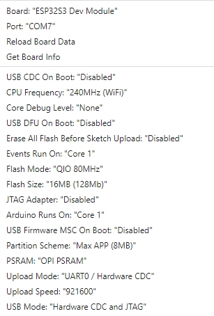
Well, now I have figured it out - I needed to change my board settings to match what this person had on your other thread:
Additionally, I needed to ensure that my upload speed was set to 115200.
Then following your steps here (in your comment above):
I now have it working! Thanks for having these threads ![]()
1 Like
Thank you everyone that posted on this thread. I got this exact display and it came with nothing but the preinstalled firmware. No links to manuals or other documents, no example codes. Went to the Guition site and that takes you straight to their designer software, which didnt help with my use case.
I couldnt get the screen to initalise through Arduino. I tried almost everything. Then this thread saved mt sanity. One newly define init sequence in GFX and everything is working.
Thank you again.
Post #7 is where the magic is at. Grumps, i thank you.
Hello everyone,
I also have a problem to start the GUITION 480x480 display working.
Could you send me your working example and zipped libraries ?
I also have a problem, because in board settings I can set 8MB in partition scheme.

Dear friend, your advice is working, thank you so much!
This topic was automatically closed 180 days after the last reply. New replies are no longer allowed.