ESP8266 with built in OLED went black

Hello people

i bought an ESP8266 board recently in aliexpress i´ll attach the link below (its in spanish but it basically says NodeMCU-developement board ESP8266 with integrated OLED 0,96 inches, driver module CH340 for programming in Arduino IDE/Micropython), with an integrated YELLOW and BLUE OLED.

well here´s the thing when i pluged it in everything is fine, the oled turns on and show the message you see in the aliexpress picture showing the OLED screen pins, then i flashed it with the DAUTHER BIN code with a NODEMCU firmaware programer, then what happened was that i only saw the hello world fragment of the screen, and stayed in that state, i couldnt see the menu i was supposed to see (later i realised that code was for generic ESP8266 board conected with a oled screen NOT built in, i dont think that could damage the oled screen or the board itself)

well then i got desperate trying to see what i could do i just unpluged the device, and the oled screen went to sleep, wont even show the factory message

later i found out i could used it with the arduino IDE i set my arduino IDE to compile ESP8266 code and i downloaded all the esp8266 OLED libraries and i tried the OLED code examples (like of 100 codes and models) and nothing seems to get the OLED display show anything (and yes i set the ssddisplay() (and some others) function with my particular esp8266 board SDA and SCL pins that you see in the advertisement picture but in vain)

good news is that i tried the builtin led code and it works perfectly, so i dont think the board is damaged, after a crazy research marathon i could not find anything but headaches, tried different codes, different libraries, wrote in the google engine "esp8266 built in oled" in a millions of ways to find my particular board but it seems that the one i own is SO PARTICULAR that nobody has made content on it and im just a newbie in this subject

so im asking for your help on how to make the oled screen turn on again with an arduino code (or bin)(no matter if it's just a simple "hello world" ) , to help me know what im doing and done wrong, if i need to install something else, or if you know a community that has made codes for THIS ONE OF KIND BOARD, i will be very thankful with you

Regards !

https://es.aliexpress.com/item/1005006272605417.html?spm=a2g0o.detail.pcDetailTopMoreOtherSeller.3.48c7j4Fsj4Fst7&gps-id=pcDetailTopMoreOtherSeller&scm=1007.40050.354490.0&scm_id=1007.40050.354490.0&scm-url=1007.40050.354490.0&pvid=e4864b35-4585-498b-8ceb-1d7011b508fe&_t=gps-id:pcDetailTopMoreOtherSeller,scm-url:1007.40050.354490.0,pvid:e4864b35-4585-498b-8ceb-1d7011b508fe,tpp_buckets:668%232846%238116%232002&isseo=y&pdp_npi=4%40dis!ARS!3504.14!2174.10!!!4.11!2.55!%402101c5b217109010623287587efa09!12000036557611226!rec!AR!!AB&utparam-url=scene%3ApcDetailTopMoreOtherSeller|query_from%3A

Welcome to the forum

Some advice for you

When posting here don't do as you have and post a slab of text with no sentences and paragraphs. Doing so make the post difficult to read and users will soon move on without reading it all as I did

I realise that your native language is not English but surely Spanish text uses sentences and paragraphs

3 Likes

Edited, thanks for the advice, please share it and if know someone who could help fix this issue I'll be appreciated

Regards

1 Like

That is much better, thank you. Now I might even read it all

1 Like

It is possible you destroyed the display. Did you connect or disconnect anything to the board? Also what did you connect to the board?

1 Like

Omg really? How? Can you explain me please

What I did was: I connected some buttons to the ESP8266 following a tutorial (link below) (literally I did it that exact way(the buttons only) (in the same pins) , not paying attention my board was different)

I had plugged it on my computer, installed the firmaware, after not seeing the expected result and pressing the buttons i just decided to unplugged it and then when I plugged it back to my computer the screen wont turn on(note that after the firmware had been installed, and after pressing the buttons, the screen was still working, I only saw a freezed hello world message)

https://m.youtube.com/watch?v=YE0FsV36ugc

I do not know that display but I2C needs pull ups, about 3.3K to operate properly. I did not see any on the link. Without a schematic or data sheet for the display I would say try this, it will not hurt anything. Also run the I2C scanner and what it tells you.

1 Like

Sorry I forgot to tell you in the minute 1:08 is the schematic, and I actually did ran the i2c scans, but one worked and the other didnt

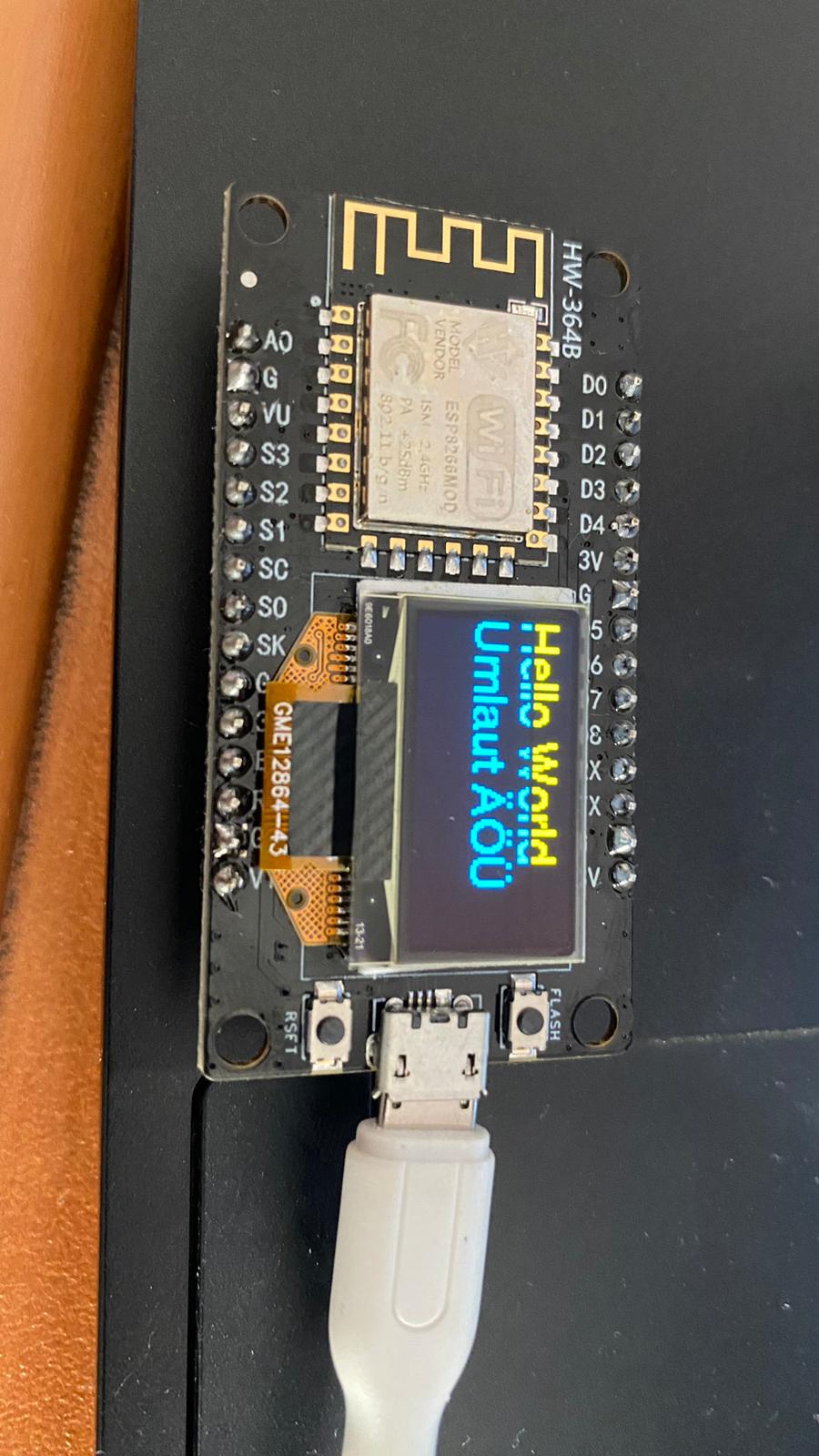
the first i tried was this one (i think its a generic scanner because its so easy and common to find), in the pins 6 and 5, that correspond to the built in OLED screen :

// Copy from Arduino Playground - i2c_scanner
// https://playground.arduino.cc/Main/I2cScanner/
// --------------------------------------
// i2c_scanner
//
// Version 1
//    This program (or code that looks like it)
//    can be found in many places.
//    For example on the Arduino.cc forum.
//    The original author is not know.
// Version 2, Juni 2012, Using Arduino 1.0.1
//     Adapted to be as simple as possible by Arduino.cc user Krodal
// Version 3, Feb 26  2013
//    V3 by louarnold
// Version 4, March 3, 2013, Using Arduino 1.0.3
//    by Arduino.cc user Krodal.
//    Changes by louarnold removed.
//    Scanning addresses changed from 0...127 to 1...119,
//    according to the i2c scanner by Nick Gammon
//    https://www.gammon.com.au/forum/?id=10896
// Version 5, March 28, 2013
//    As version 4, but address scans now to 127.
//    A sensor seems to use address 120.
// Version 6, November 27, 2015.
//    Added waiting for the Leonardo serial communication.
// 
//
// This sketch tests the standard 7-bit addresses
// Devices with higher bit address might not be seen properly.
//

#include <Wire.h>


void setup()
{
  Wire.begin(5,4);  //Modifed for ESP32

  Serial.begin(9600);
  while (!Serial);             // Leonardo: wait for serial monitor
  Serial.println("\nI2C Scanner");
}


void loop()
{
  byte error, address;
  int nDevices;

  Serial.println("Scanning...");

  nDevices = 0;
  for(address = 1; address < 127; address++ ) 
  {
    // The i2c_scanner uses the return value of
    // the Write.endTransmisstion to see if
    // a device did acknowledge to the address.
    Wire.beginTransmission(address);
    error = Wire.endTransmission();

    if (error == 0)
    {
      Serial.print("I2C device found at address 0x");
      if (address<16) 
        Serial.print("0");
      Serial.print(address,HEX);
      Serial.println("  !");

      nDevices++;
    }
    else if (error==4) 
    {
      Serial.print("Unknown error at address 0x");
      if (address<16) 
        Serial.print("0");
      Serial.println(address,HEX);
    }    
  }
  if (nDevices == 0)
    Serial.println("No I2C devices found\n");
  else
    Serial.println("done\n");

  delay(5000);           // wait 5 seconds for next scan

but what i got in the serial was only non sense garbage letters (i also change the baud rate to 115200, and got some letters, but nothing useful)

then after some more research i tried this different scanner that does the same, but it will show all the pins in the serial, this one actually gave me the right results, that the pins 6 and 5 were a i2c device at adress 0x3c

/* 
* i2c_port_address_scanner
* Scans ports D0 to D7 on an ESP8266 and searches for I2C device. based on the original code
* available on Arduino.cc and later improved by user Krodal and Nick Gammon (www.gammon.com.au/forum/?id=10896)
* D8 throws exceptions thus it has been left out
*
*/


#include <Wire.h>

void setup() {
  Serial.begin(115200);
  while (!Serial);             // Leonardo: wait for serial monitor
  Serial.println("\n\nI2C Scanner to scan for devices on each port pair D0 to D7");
  scanPorts();
}

uint8_t portArray[] = {16, 5, 4, 0, 2, 14, 12, 13};
//String portMap[] = {"D0", "D1", "D2", "D3", "D4", "D5", "D6", "D7"}; //for Wemos
String portMap[] = {"GPIO16", "GPIO5", "GPIO4", "GPIO0", "GPIO2", "GPIO14", "GPIO12", "GPIO13"};

void scanPorts() { 
  for (uint8_t i = 0; i < sizeof(portArray); i++) {
    for (uint8_t j = 0; j < sizeof(portArray); j++) {
      if (i != j){
        Serial.print("Scanning (SDA : SCL) - " + portMap[i] + " : " + portMap[j] + " - ");
        Wire.begin(portArray[i], portArray[j]);
        check_if_exist_I2C();
      }
    }
  }
}

void check_if_exist_I2C() {
  byte error, address;
  int nDevices;
  nDevices = 0;
  for (address = 1; address < 127; address++ )  {
    // The i2c_scanner uses the return value of
    // the Write.endTransmisstion to see if
    // a device did acknowledge to the address.
    Wire.beginTransmission(address);
    error = Wire.endTransmission();

    if (error == 0){
      Serial.print("I2C device found at address 0x");
      if (address < 16)
        Serial.print("0");
      Serial.print(address, HEX);
      Serial.println("  !");

      nDevices++;
    } else if (error == 4) {
      Serial.print("Unknow error at address 0x");
      if (address < 16)
        Serial.print("0");
      Serial.println(address, HEX);
    }
  } //for loop
  if (nDevices == 0)
    Serial.println("No I2C devices found");
  else
    Serial.println("**********************************\n");
  //delay(1000);           // wait 1 seconds for next scan, did not find it necessary
}

void loop() {
}

in which pin should i conect the pull ups?

thanks for the answers, regards

The garbage letters are typical of a baud mise match. The ESP devices boot up to a much higher baud rate (probably because of test time) and switch to the baud rate you set in your code. I always use at least a 3 second delay before setup prints anything on the terminal.

The Pull up resistors go on SCL and SDA. Reason these are open drain / open collector buses. They cannot put out a high, they turn off and let the pull up resistors pull the bus high.

You are welcome. Hope it will run perfectly for you. I modified my scanner software so it repeats, sometimes I find an intermittent response.

1 Like

Hi, sorry the delay (just came from a collegue class lol)

well i added the pull up resistors (didnt have 3.3k, so i used 10k instead, i dont think it will make any difference, will it?) as comanded to SCL and SDA pins and conected them to ground, and the screen is still off, :frowning: , any other ideas? TT

do you have a very simple OLED software i can try? because as i told you the fact that one I2C scanner worked and the other didnt makes me suspect its a software thing, but well im still a newbie, what do you think?

regards

There are several I2C scanners available and they do not all work on all 'Arduino' platforms. Many of them were written before the ESPs were made available. Use the one that gave you the value.

10K may be enough, I like about 1mA flowing. Without a scope you cannot be sure. However if one of the scanners is consistent then they are OK at that temperature.

1 Like

Did you add pull-downs instead of pull-ups?

2 Likes

Actually I'm not sure, I just connected the resistor between sda scla pins and ground, with no results , I was afraid of connecting it to 3.3v or 5v pin that would certainly destroy the screen, can you provide me an example squematic? Again I'm just a newbie

And I found another user who faced a really alike problem like me (link below), idk if he's going to answer, I tried his method but didn't work

And as far as he says, he had no need of using pull ups/downs, that makes my not-working-software (or wrong-variable-value) suspecs even greater

Idk maybe I'll have to try set all the pins pairs in the sssd1603 display function, to see if there's a mistake in the esp8266 advertisement picture, I'll do it when I have time (a lot of colleague homework piling up)

Again Thanks for the help guys, regards

1 Like

Hello Miguel,

I received an email from you so I thought let me respond.

The problem was really the different PIN numbers as I posted earlier. I hope you didn’t solder any component to your board, it’s just software problem.

Also be sure to use the right library.

Take a deep breath and relax.
Start over again step by step. The problem is really different pin numbers, not pull up/down or I2C.

If you doesn’t work for you, I’ll send you the source code I used.

2 Likes

Hi thanks for answering, I would really appreciate that you upload the code you used and the library.

I'm using the ESP8266 and ESP32 OLED driver for ssd1306 displays (even try Adafruits displays)

and i didn't solder anything, im really certain it's a software thing, but I tried the pins sda and scl that were advertised with no results even used similar products pins and nothing

Did you modify the SSDWire display() with your corresponding pins, right? Or you did something else?, maybe I'm not modifying the right function

Thanks for answering

Hello, I'm having the same problem. I bought the ESP8266 HW-364B card two days ago and when I connected it to the computer, the factory text appeared on the OLED screen. I submitted a code but nothing changed. When I unplugged the power cord and plugged it back in, the factory labels disappeared. I did some research on the internet and adjusted the code according to the SCL (D5) and SDA (D6) pin numbers of the card I bought, but I still could not print text on the screen. If anyone solves the problem and explains it, I would be grateful.

1 Like

Hi,as Aldev said before it's probably the libraries were using or not configuring the code right

Let's wait for Aldev's answer for the library and code configuration, meanwhile keep trying OLED libraries to see if you can get the screen work

Regards

SOLVED!, After browsing through several online shops advertising the same product i´ve finally found a code that worked (i dont know why, guess i´ll have to study it later)

Procedure:

1-Install these libraries outside arduino:

GitHub - olikraus/U8g2_for_Adafruit_GFX: Add U8g2 fonts to any Adafruit GFX based graphics library.

GitHub - adafruit/Adafruit_SSD1306: Arduino library for SSD1306 monochrome 128x64 and 128x32 OLEDs

2-Install adafruit GFX library (along with the BUS thing) inside arduino

3- Paste this code (got it from an user in an online shop)(you can find it in the example U8G2_For_adafruit_gfx sketches with the name "Hello_Adafruit_SSD1306", but some lines of code needs to be added!!!, the one i pasted is the complete version)

/*

  Hello_Adafruit_SSD1306.ino

  Demonstrates how to connect U8g2_for_Adafruit_GFX to Adafruit SSD1306 library.

  U8g2_for_Adafruit_GFX:
    - Use U8g2 fonts with Adafruit GFX
    - Support for UTF-8 in print statement
    - 90, 180 and 270 degree text direction
  
  List of all U8g2 fonts: https://github.com/olikraus/u8g2/wiki/fntlistall
      
*/
#include <Wire.h>
#include <Adafruit_SSD1306.h>
#include <U8g2_for_Adafruit_GFX.h>

#define SCREEN_WIDTH 128
#define SCREEN_HEIGHT 64
#define OLED_RESET -1
#define SCREEN_ADDRESS 0x3C

Adafruit_SSD1306 display(SCREEN_WIDTH, SCREEN_HEIGHT, &Wire, OLED_RESET);
U8G2_FOR_ADAFRUIT_GFX u8g2_for_adafruit_gfx;

void setup() {
  Wire.begin(14,12);
  display.begin(SSD1306_SWITCHCAPVCC, SCREEN_ADDRESS);
  u8g2_for_adafruit_gfx.begin(display);                 // connect u8g2 procedures to Adafruit GFX
}

void loop() {  
  display.clearDisplay();                               // clear the graphcis buffer  
  u8g2_for_adafruit_gfx.setFont(u8g2_font_helvR14_tf);  // select u8g2 font from here: https://github.com/olikraus/u8g2/wiki/fntlistall
  u8g2_for_adafruit_gfx.setFontMode(1);                 // use u8g2 transparent mode (this is default)
  u8g2_for_adafruit_gfx.setFontDirection(0);            // left to right (this is default)
  u8g2_for_adafruit_gfx.setForegroundColor(WHITE);      // apply Adafruit GFX color
  u8g2_for_adafruit_gfx.setCursor(0,20);                // start writing at this position
  u8g2_for_adafruit_gfx.print("Hello World");
  u8g2_for_adafruit_gfx.setCursor(0,40);                // start writing at this position
  u8g2_for_adafruit_gfx.print("Umlaut ÄÖÜ");            // UTF-8 string with german umlaut chars
  display.display();                                    // make everything visible
  delay(2000);
} 

4-Enjoy

PD1: also changed the upload speed in the tools tab to 921600 , but i dont think that made any difference

PD2: as an advice (if this didn't work for you) I would recommend you to search through other online shops or other sellers for the SAME-LOOKING board you're struggling to make work, check the comments of the product and if you see a code paste it or copy it by hand (or maybe look for other websites/users who have worked with the SAME-LOOKING board you're using, also might help) this way you'll save a great amount of time trying useless stuff

PD3: I'll also leave two photos from a seller to make it work, in case it's useful for you (the seller I bought it from didn't actually include those)


Well, to close this topic, i dont actually know why this particular code works, so dont ask me hahaha, its up to you to study it, but its certainly a relief to know the screen is not dead, it was all a matter of faith

Good night guys, thanks for everything, I really appreciate your help, now we can sleep very soundly

3 Likes


miguel_t1111 Thanks to you, my problem was solved. Thank you for your help.

1 Like

I'm glad it worked furkankoc42, another PD after studying a little the code,I found the actual SDA and SCL pins are 14 and 12 respectively(I guess you've have also realized it, but if not here you are) (obviously I'm not buying from that seller again hahaha) and this works for all the codes I thought were useless ,in case you're curious, as Aldev remarked earlier

And also pasting this block of code to all adafruit libraries make it work as well

#include <Wire.h>
#include <Adafruit_SSD1306.h>
#include <U8g2_for_Adafruit_GFX.h>

#define SCREEN_WIDTH 128
#define SCREEN_HEIGHT 64
#define OLED_RESET -1
#define SCREEN_ADDRESS 0x3C

Adafruit_SSD1306 display(SCREEN_WIDTH, SCREEN_HEIGHT, &Wire, OLED_RESET);
U8G2_FOR_ADAFRUIT_GFX u8g2_for_adafruit_gfx;

void setup() {
  Wire.begin(14,12);
  display.begin(SSD1306_SWITCHCAPVCC, SCREEN_ADDRESS);
  u8g2_for_adafruit_gfx.begin(display);                 // connect u8g2 procedures to Adafruit GFX
}

Regards