External interrupts assigned to the wrong pins?

I've been scratching my head all day as to why my tachometer code wasn't working, and I just realized that I could fix the issue by switching the pin (or interrupt value).

Basically, my configuration has D2 tied to interrupt INT1 and D3 tied to INT0.

Is this a normal thing to run into? Is it possible that I somehow swapped these assignments without realizing it? This is very confusing because I would have thought that these assignments would have been universal.

No, in the AVRs those interrupts are hard-wired to their pins. You can't reassign them.

Use:

... to let the compiler figure out the right one.

That's what's funny. I WAS using that format originally, but I had to swap them to get it to work.

I have one external interrupt wired into D3, and this code does NOT work:

#define ZCP 2            
#define TACHO 3          

unsigned int RPM;                   // real rpm variable
volatile unsigned int count;                 // tacho pulses count variable
unsigned long lastflash;

void setup() {
  Serial.begin(115200);
  attachInterrupt(digitalPinToInterrupt(TACHO), tacho, FALLING);   
}

I have to either swap the pins I'm using, or change the interrupt value to 0.

I have nothing connected to D2, and the numbers are erratic. When I try this code:

#define ZCP 2            
#define TACHO 3          

unsigned int RPM;                   // real rpm variable
volatile unsigned int count;                 // tacho pulses count variable
unsigned long lastflash;

void setup() {
  Serial.begin(115200);
  attachInterrupt(digitalPinToInterrupt(ZCP), tacho, FALLING);   
}

...all of a sudden it works.

Again, nothing connected to D2, only D3, and INT0 is the only one that works. I can swap it over to D2, and INT1 is the one with the correct values.

It works the same by setting the interrupt value manually: D3 -> INT0, D2 -> INT1.

I was just wondering if this was a common issue, or if I'm the only one.

Are you reading the pin number from the board, or counting pins. Remember the pins start at D0. It sounds like you are counting pins starting at D1 instead of D0.


D3 as marked on the board -> INT0: Correct readings
D3 as marked on the board -> INT1: Incorrect/erratic readings
D2 as marked on the board -> INT0: Incorrect/erratic readings
D2 as marked on the board -> INT1: Correct readings

Trust me, I went over this 100 different ways to verify that I wasn't crazy. lol

Which MCU board is that? Please post a link to the product page.

For the ATmega328 series, D2 (bit 2, PORTD) = INT0 and D3 (bit 3, PORTD) = INT1.

In that picture, you are plugged into D3 or INT1. That is a NANO right?

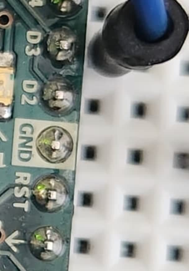
Your wiring must be incorrect, but it is impossible to see the mistake from the photo. Post a hand drawn wiring diagram, with pins and connections clearly labeled.

In the picture, that is plugged into D3, which is, for whatever reason, tied to INT0. Yes, it's a Nano, bought from that link above.

Your solder work looks a bit sketchy. Whaty temp are you using, what kind of solder?

How are the pins driven? Does the tach positively drive them to 0 or 5V or are they floating inputs and would be erratic unless there's some external or internal pullup-or-pull-down? Maybe:

I bought this with headers already attached from this website. I don't know what they used.

Show all the code. I need to see the pinmode statement

1 Like

Have you used a soldering iron on any of those pins in the picture?

Along with your hand drawn wiring diagram, please post all the code, using code tags, and describe or post a link to the electronics module connected to D2 and D3. Did you connect all the grounds?

Post a pic without the blue and yellow wires obscuring the view of the MCU IC so we can see which PCB trace is going to which IC pin.

I'm using a function generator to create the 60Hz 5Vac signal.

The "square wave" is what's being sent to D3 currently from the H11A1:

The code I've been using to troubleshoot (This is the one that is working for the D3 pin):

#define ZCP 2            
#define TACHO 3          

unsigned int RPM;                   // real rpm variable
volatile unsigned int count;                 // tacho pulses count variable
unsigned long lastflash;

void setup() {
  Serial.begin(115200);
  attachInterrupt(0, tacho, FALLING);   
}


// RPM counting routine
void tacho() {
  count++;
}

int samplingTime = 1000;
float lastSample = millis();
void loop() {
  float currentSample = millis();
  if ((currentSample - lastSample) > samplingTime) {
    int checkCounter = count;
    long tachotime = micros() - lastflash;
    if (tachotime == 0) {
      tachotime = 0.01;
    }
    float time_in_sec  = (float)tachotime / 1000000;
    RPM = (((checkCounter)  / time_in_sec) * 60);
    Serial.println(currentSample - lastSample);
    Serial.println(count);
    count = 0;
    lastflash = micros();
    lastSample = millis();
  }
}

My reading (Again, D3 is the pin):

These values are correct. 120 count since it's reading the voltage upswing and downswing.

They go erratic when I switch to INT1:

you are supposed to use digitalpintointerrupt, NOT a number! That is why we ask to see ALL the code.

attachInterrupt(digitalPinToInterrupt(pin), ISR, mode) (recommended)

[sterretje edit]
swearing / insult removed
[/edit]