Hi everyone,
This is the second PCB I've done in KiCad and although I'm feeling way more confident I am very new to this. I am not an electrical engineer so some of my logic / thinking may be very flawed but I'm loving the learning curve and would love any feedback.
Firstly this may be over engineered or over complicated but I really don't want this device to fail so I'm trying to make sure it doesn't and I at least know when it fails early.
This device controls is part of a beverage manufacturing system I built. Basically as the beverage is made it dumps into a small tank. When that tank fills up it triggers a pump that moves the liquid into a larger tank. Currently it runs of float switches however they get stuck and have failed in the past. I am adding a liquid inlet solenoid in the new system so I can shut it off if something fails..
One of the biggest problems im trying to solve is human error in setting up the machines which can lead to failures. Some examples have been ... air in the pump and unable to move liquid / non return valve put the wrong way around / value left closes ect. Most are human error and I want a system that can tell a failure has occurred and shut off the inlet solenoid.
The system I have designed has 3 levels of redundancy. The first level runs off a set of RS232 scales the tank sits on as well as a ultrasonic sensor to gauge water level. This feeds into an ESP32 that will trigger a SSR, activating the pump to drain at a certain level.
The second level is a 555 bistable timer setup similar to this.

The 2nd level is a failsafe that is not dependant on the ESP32 incase the ESP32 crashes for what ever reason.
The 3rd level is a solenoid valve on the inlet to shut the system off that is designed to trigger when the ESP32 can sense that something is wrong ie. liquid is not draining properly / pump has failed.
The way I see it working is the following. Say the tank is 30 litres. Lvl 1 will trigger from 15L down to 5L using the scales (backed up by ultrasonics sensor). Lvl 2 will only occur if the ESP32 fails at its job and the probes will be set between 25L and 15L. Lvl 3 will only trigger when the top prob is triggered for more than 30 seconds and then close the solenoid and stopping the flow completely.
This device will be connected to a MQQT server so my plan is to have alerts if Lvl 1, 2 or 3 is triggered.
Here is my schematic.

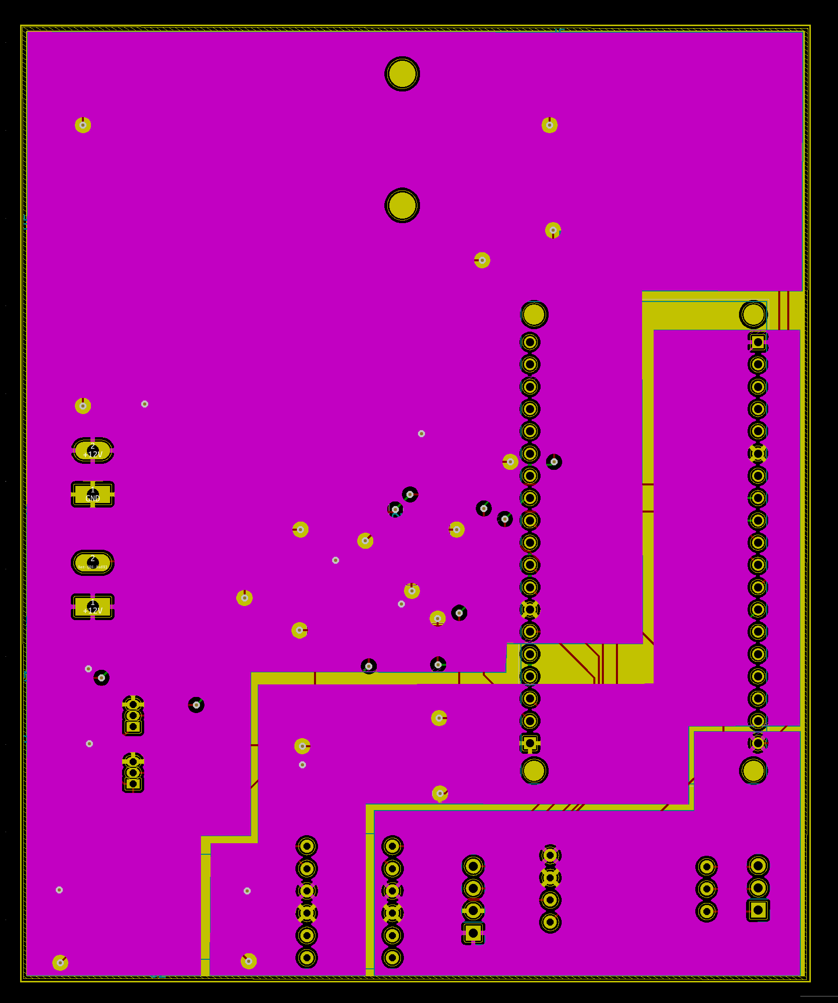
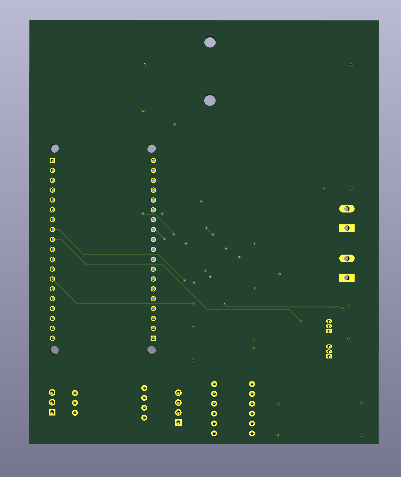
PCB:
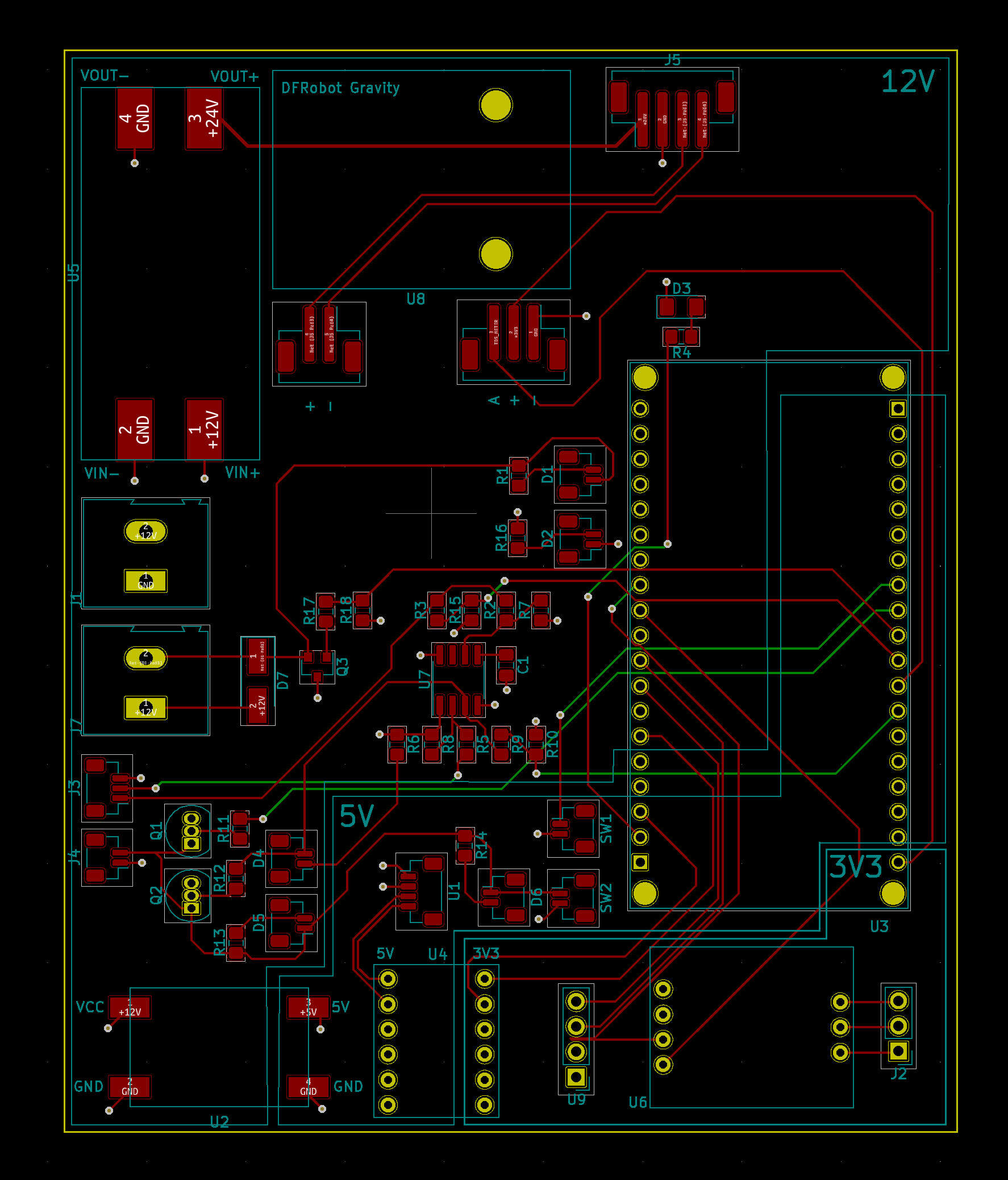

Some of the aspects I think I may have messed up are the voltage dividers of the 555 timer trigger and some resistors maybe not be correct.
I hope that makes sense. Thank you in advance, and any feedback would be very appreciated.