I have i circuit (from an appliance) where a 501B-8P triggers a buzzer. I'm tapping the VCC and GND from the buzzer to an optcoupler which triggers a GPIO. but while not beeping, VCC and GND gets very fast surges, under 3V3, not enough to make the buzzer beep, but enough to trigger the optocoupler. Is there a way to make a filter blocking any voltage under 3V3, so even 3V1 would not pass?
This is the original appliance board. by left blue and brown wires 220VAC, Led is for on/off status and the buzzer beeps when finish.
So i hooked from the buzzer, (sencond picture) orange wire GND and brown wire 3V3VCC.
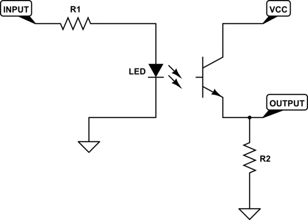
The optocoupler uses this design, non inverting pull down.
But noise makes the optocoupler trigger even if the buzzer does not beeps.
I tested it having a led with 220R on R1 (input), 10K on R2 (output) and many times the led lighted very dim having the buzzer silent, and when the buzzer beeped, led lighted right.
You can put a diode (or perhaps an LED) in series with the optocoupler to prevent 3.1V from triggering it and then tune in the resistor for a suitable current level when you reach 5V.
The LED voltage drop will reduce the effective voltage reaching the opto. Look at the opto specs to see how much current in the internal LED will push the transistor into conducting mode, and what is its forward voltage, that added to the forward voltage of the selected external diode/LED will prevent conduction. Voltage drop of Red LEDs typically are around 1.6V, while White ones are around 3V.
You can also use a voltage comparator, but I guess that would be a little more elaborate
6 1N4007 diodes at the same time? A quick test shows that the combined voltage drop for the 6 diodes would be between around 3.7 and 4.4V, depending on the current, as expected.
If apply 5V to the above setup I get a current of about 400µA, enough to light the red LED dimly. I should try with a lower resistance. IF I lower the voltage to 3.1V, the leakage current drops to 0.4µA
This should work for input voltages between 3.1 and 5V. A white LED has a voltage drop of around 3V, and the one of the internal LED of the 4N25 is about 1.3V for a current of 10mA.
Both voltage drops in series should allow for a negligible current when the spikes get to 3.1V.
When the input voltage raises to 5V, the current is limited by R. you have to experiment with R. My tests worked with 4.7Ω