When calculating the deflection of a simply supported beam using Arduino ESP8266 and HX711 amplifier, three resistors of 120 ohms, and one strain gauge with a resistance of 120 ohms.
I'm trying to make a stem.
The problem I currently have is that the sensor value only shows -1 or 0.
It is not possible to calculate the slight deflection of a solid wooden bar by amplifying the signal using the HX711 amplifier.
I expect there will be no problem with modifying the signal terminal to match the code and reinstalling it.
The HX711 library used was created by Rob tillaart, and we expect there will be no problems.
The code to use is also very simple, so I don't expect any problems.
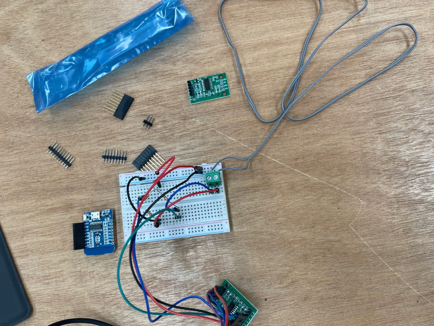
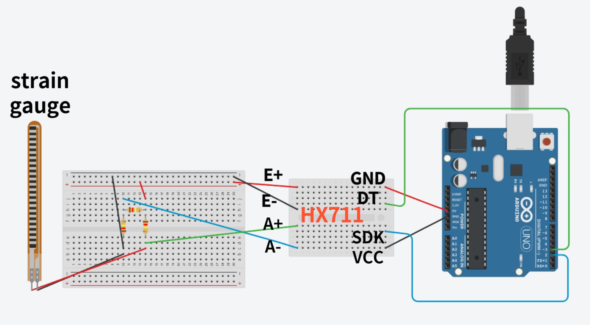
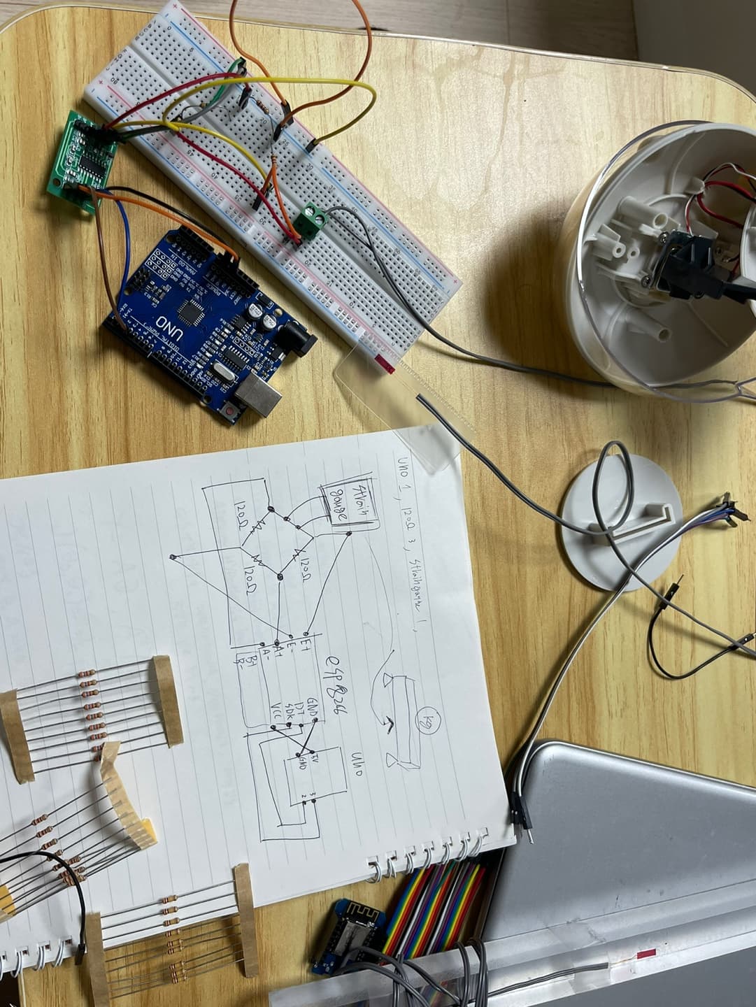
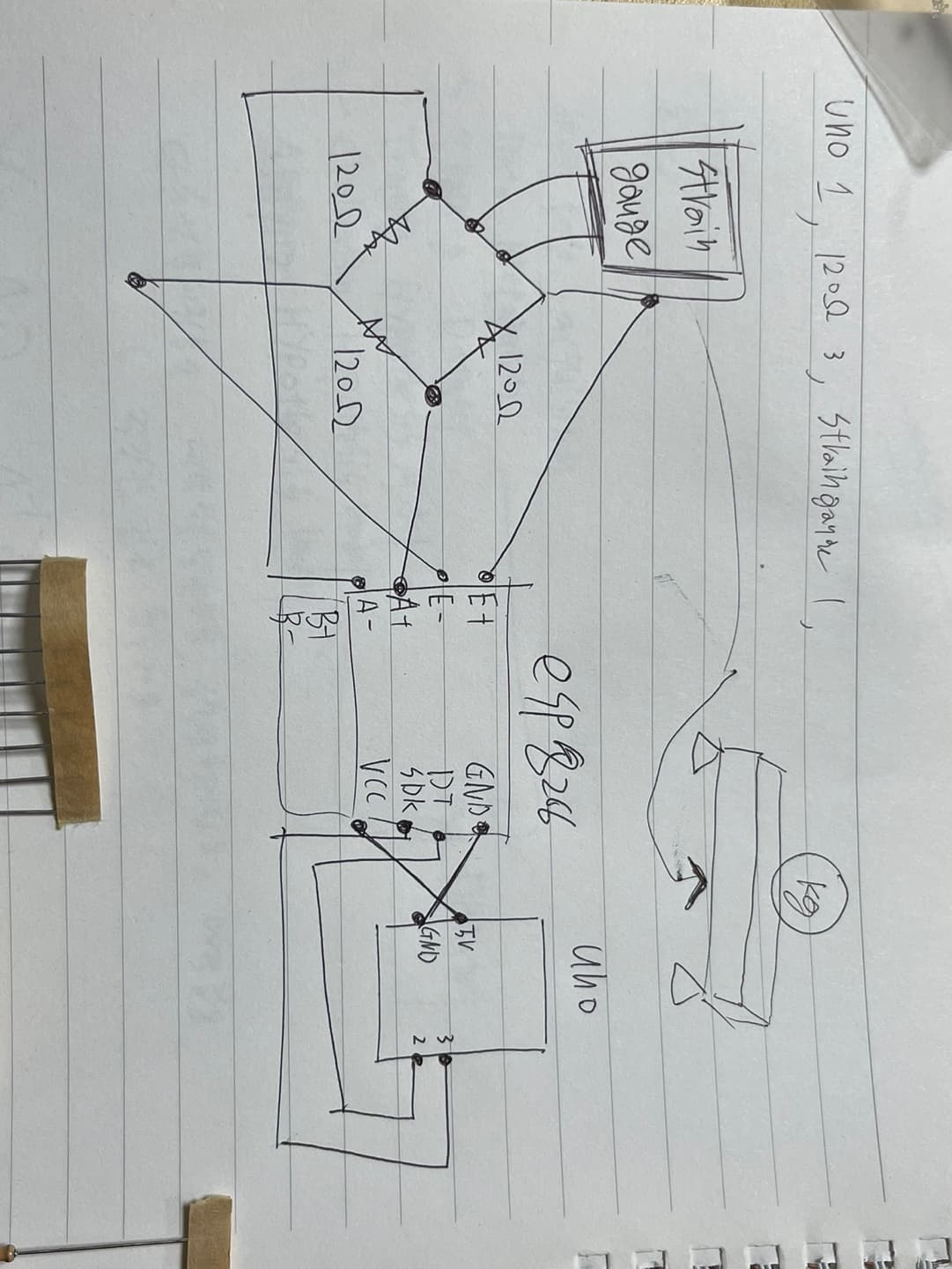
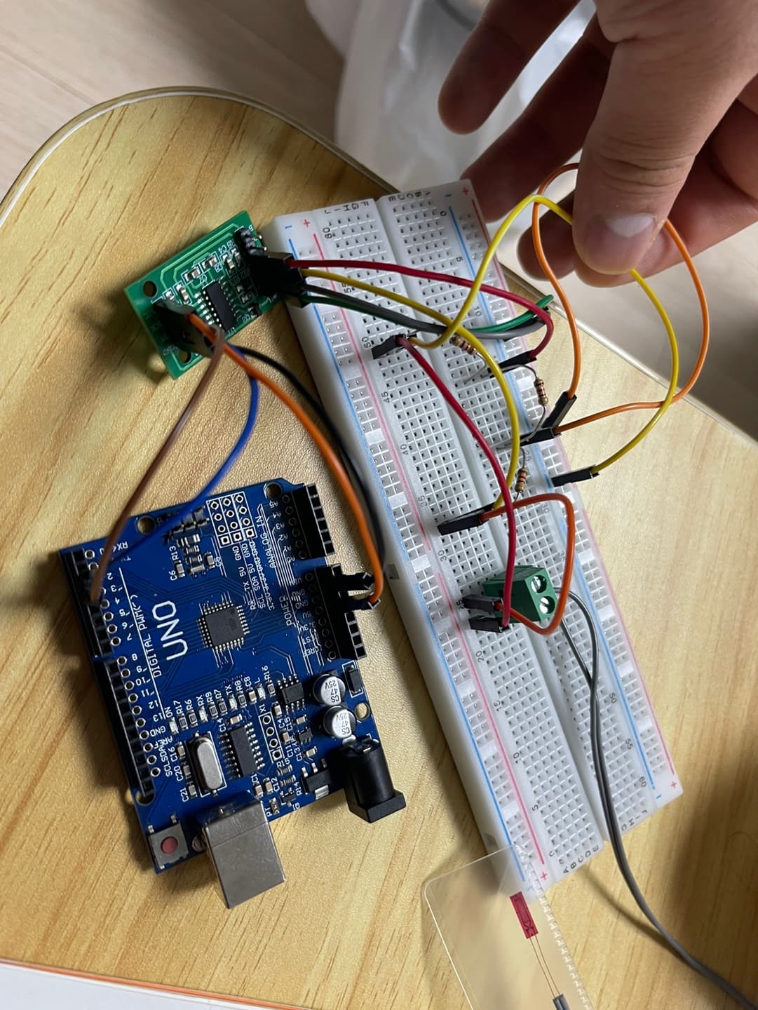
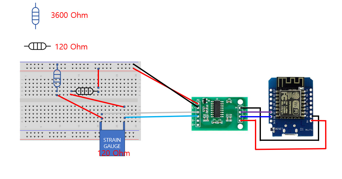
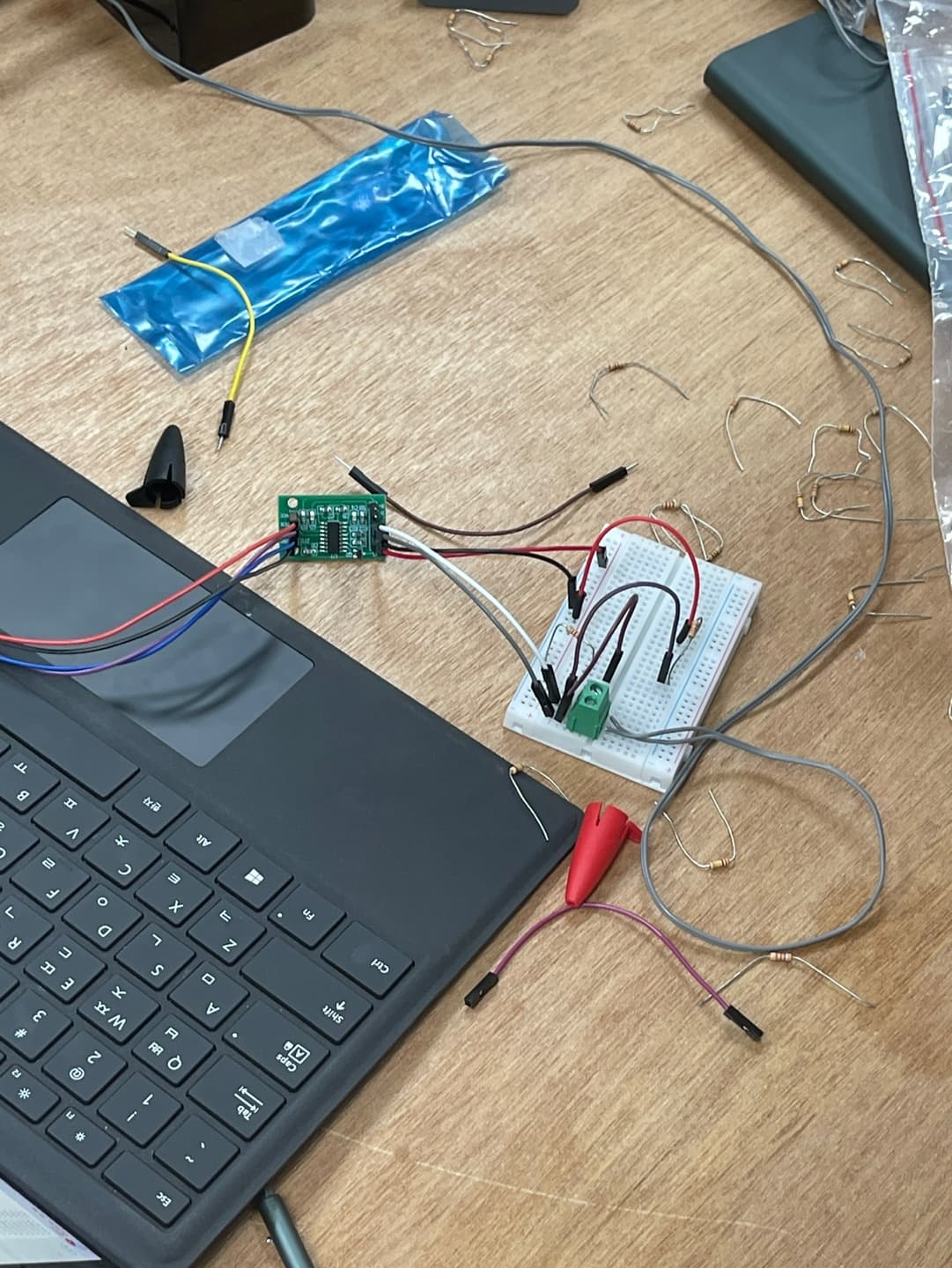
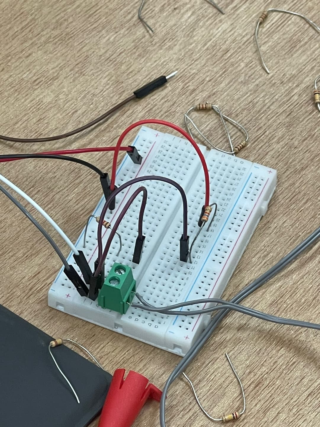
I will attach the actual circuit and circuit structure diagram.
There is no proper data for the structural diagram, so I would like to ask you to check the actual photo.
I would really appreciate your help.
First of all, thank you for your help.
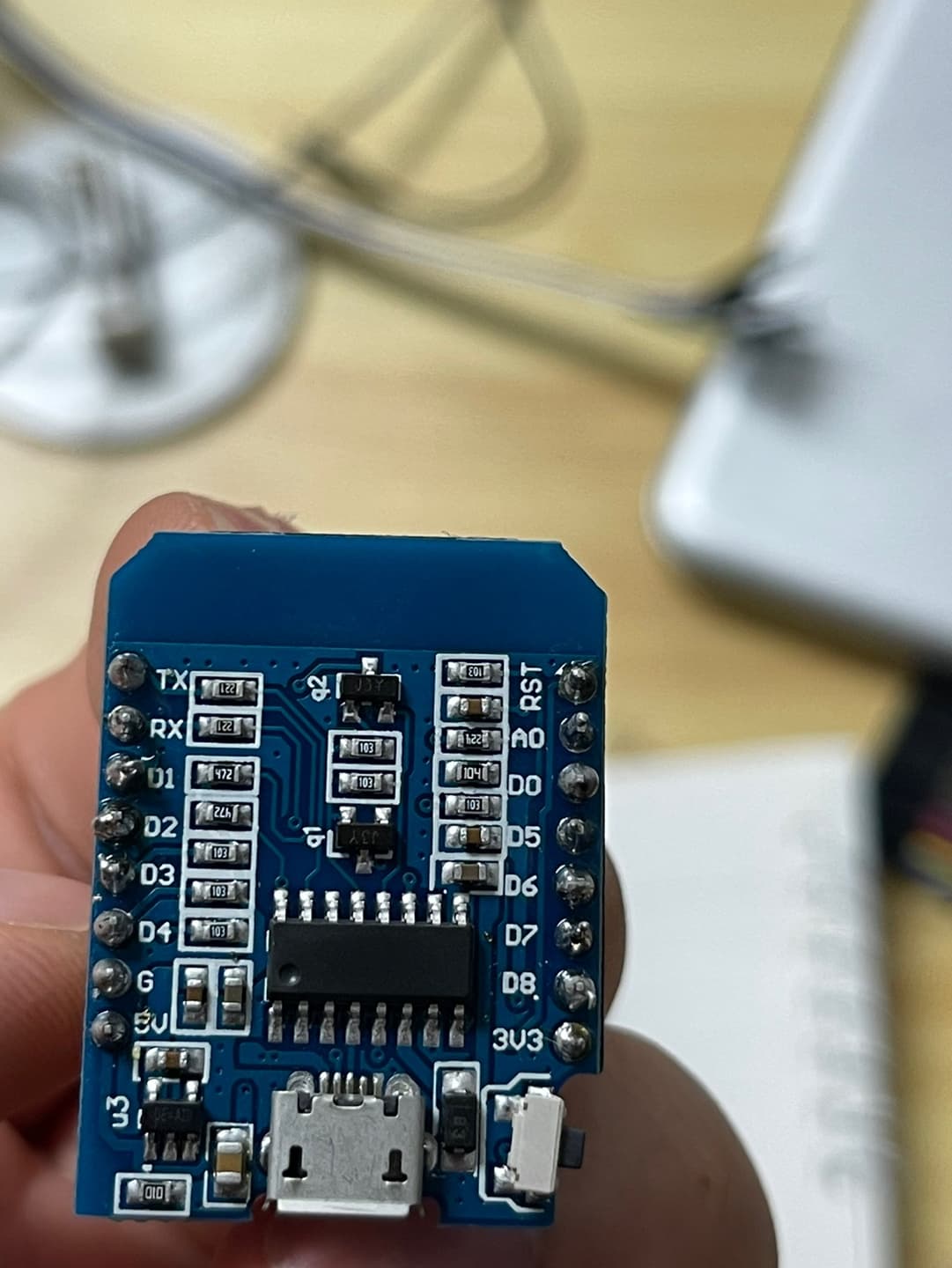
I currently have two boards: Arduino UNO and ESP8266 (WIFI model).
For the circuit diagram, there were no pictures of the ESP8266, so I had to use a picture of the UNO board.
So, I think the reason it has a number like D1 is because it is tested using two boards.
There will be no problems with the code because the code is modified each time the board is used alternately.
The reason the code contains "**" is because it's my first time using the forum.
It seems that after adding BOLD to emphasize the code, I was unable to correct it because I confirmed that there was a code notation function.
I suspect there may be a problem with the circuit. Are there any expected problems?
Can you please post a copy of your circuit, a picture of a hand drawn circuit in jpg, png?
Hand drawn and photographed is perfectly acceptable.
Please include ALL hardware, power supplies, component names and pin labels.
... and actual measurements of the wheatstone bridge resistances & voltage difference going into the HX711.
Yes -- If your wheatstone bridge isn't balanced well, the output to the HX711 will peg to one end of the range, and then screw up any tare or calibration operations.
I should have used the 8266 board, but it didn't work, so I used the UNO board I used before.
I honestly don't know if it's compatible.
I apologize for the messy wiring of the actual circuit.
@DaveX
The currently uploaded photo doesn't look good, but can you give me some advice on what improvements should be made to the current circuit so that it can be measured clearly?
I am a student majoring in ship and marine engineering, not electronic engineering, so my understanding of circuits is very limited.
What code are you using? Are you printing the raw readings or something that has been tare()ed or calibrated.
Are the 120 ohm resistors actually 120 ohms? If they are off by 5%, the Wheatstone bridge output millivolts into the HX711's A+/A- could exceed the +/-20mV, pegging the readings to a constant value at the limits, whnich, if tare()-ed would produce readings of 0.
Use a DMM and measure the A+/A- voltatge to see if it is in the +/-20mV range. If it isn't in range, pull each resistor, measure its exact resistance (and also the resistance of the strain gauge)
If one resistance is 126 ohms and all the rest are 120, then for a 5V E+/E- you'd get 5*(120/240 - (120/(126+120)))=60mV The resistances all need to be better than 120.0+/-1.0 to move the A+/- voltage down to the 10mV level.
@DaveX
The code used the code in the comments above.
I think you will receive pure sensor values rather than processing the sensor values separately.
Due to the nature of the Wheatstone bridge, I expect the sensor value to change when I touch a 120 ohm resistance rather than a strain gauge.
Also, I expected that there would be a change in the value if I bent the strain gauge sensor, but since 0 was still displayed, I thought there was some problem, so I wrote this post.
By checking the completed circuit in the professor's office, we know roughly what the results will be. (It is not exact, but the value will be between 2000 and 12000.)
Resistance is 120 ohms according to the analysis of the band, and the strain gauge is also 120 ohms. When bent, it was confirmed with the professor's equipment that there was a change of about 119.8 to 120.2.
I'm not sure what a DMM is, but I don't have any equipment that can measure voltage, so I can't check if it's +/-20mV.
It has a resistance of 120 ohms and a resistance of 3600 ohms, so you can plug in additional resistors if necessary.
If bending the beam with your professor's setup gives readings between 2000 and 12000 with everything the same from the strain gauge through the HX711, then the problem is downstream in your code or in how you hook the HX711 to your arduino.
@herbschwarz
I also don't know the exact reason.
The completed circuit owned by the professor, the codes used, and the reference materials were all connected to digital pins, but various values other than 0 and 1 came out, so the process was repeated.
@DaveX @TomGeorge
First of all, I really appreciate your help until late.
While searching for information at school, I found something that might be helpful.
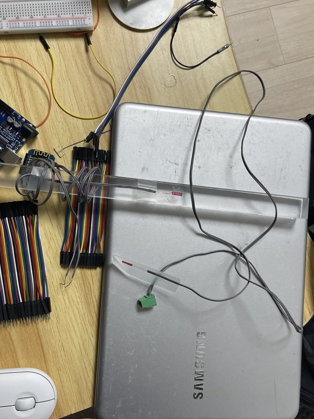
In the case of the photo, it is a completed version of the project and is a photo of a circuit designed by the professor and only possessed by the professor to calculate deflection.
I also saw a demonstration, and the code below is the code the professor used.
I don't know what it means due to my lack of electrical engineering knowledge, but I disassembled the existing circuit and connected it to the structure in the photo.
Only 0 is still displayed on the serial monitor.
I searched for data and did preliminary research on various cases, but there is a problem with the sensor values, and the situation is not working for all of the 20 students working on the project, and only the professor is involved, so I honestly don't know what the problem is.
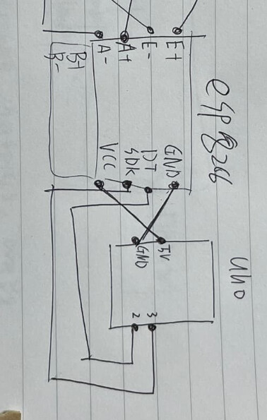
It looks like the output of the amplifier is I2C and the UNO I2c pins are A4 SDA (data) and A5 SCL (clock) and the common ground. [Pull-up resistors may be required.]