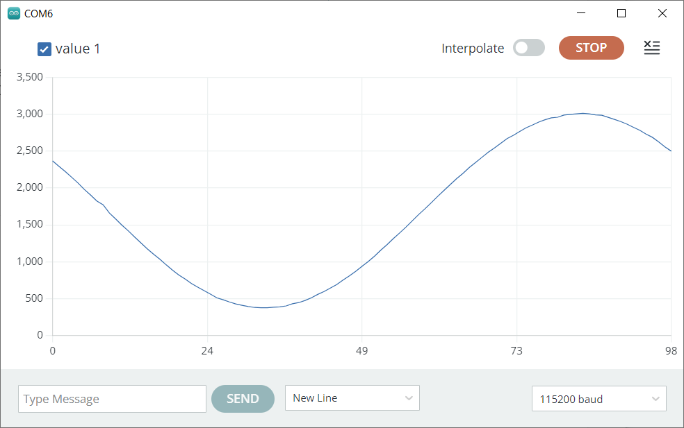
I am trying to develop a time domain reflectometer. However am stuck one issue and that is to find the rise time of a sinosoidal wave. Attached picture shows the rise time iam trying to measure.
I can save the serial data, print it as a graph as shown in the picture. Lets say I have an array:
{20, 20, 20, 72, 73, 76, 79, 83, 84, 85, 86, 86, 86, 86, 86, 86, 86, 86, 86};
and each data is spaced 312millisecond. how do i find the rise from 3rd(20) to 10th(86) datapoint in this array? I understand that the minimum and maximum should be found to locate the rise time, but how to find the time interval confuses me.
I am using a CD4060 signal generator and NucleoL452 to get data. Can anyone help.
<strong>prevData = newData;//store previous value
//newData = ADCH;//get value from A0
if (prevData < 43 && newData >= 43){//if increasing and crossing midpoint
period = timer;//get period from current timer value
timer = 0;//reset timer
}</strong>

**timer++;//increment timer**
experiment measuring the rise time of a 10Hz sine wave
ESP32 sampling every milliSecond
// ESP32 determine sine wave rise time

// the data acquired must be the rising edge of signal - see example sine wave plot

#include <driver/dac.h>
#include <driver/adc.h>

#define RXPIN 16

// Timer0 Configuration Pointer (Handle)
hw_timer_t *Timer0_Cfg = NULL;

// array to save 100 ADC values
#define SAMPLES 100
volatile int counter = 0, adcsIndex = 0;
;
volatile unsigned int adcs[SAMPLES] = { 0 };

// The Timer0 ISR Function (Executes Every Timer0 Interrupt Interval)
void IRAM_ATTR Timer0_ISR() {
  // read ADC output to DAC
  unsigned int adc = analogRead(35);            // read ADC pin 35
  // save SAMPLE ADC values to array
  if (adcsIndex < SAMPLES) adcs[adcsIndex++] = adc;
  dac_output_voltage(DAC_CHANNEL_1, adc >> 4);  // output to DAC
  counter++;
}

// interrupt handler - change in level on RXPIN
void IRAM_ATTR handleInterrupt2() {
  if (!digitalRead(RXPIN)) return;                // look for rising edge
  detachInterrupt(digitalPinToInterrupt(RXPIN));  // detach the interrupt
  timerAlarmEnable(Timer0_Cfg);                   // start timer
}

void setup() {
  Serial.begin(115200);
  delay(2000);
  pinMode(RXPIN, INPUT_PULLDOWN);
  attachInterrupt(digitalPinToInterrupt(RXPIN), handleInterrupt2, CHANGE);
  Serial.println("\nESP32 determine sine wave rise time");
  // Configure Timer0 Interrupt 1000/second
  Timer0_Cfg = timerBegin(0, 80, true);
  timerAttachInterrupt(Timer0_Cfg, &Timer0_ISR, true);
  timerAlarmWrite(Timer0_Cfg, 1000, true);
  //timerAlarmEnable(Timer0_Cfg);
  // Enable DAC1 Channel's Output
  dac_output_enable(DAC_CHANNEL_1);   // display on DAC?
  analogSetWidth(12);                 // ADC 12bit resolution
  analogSetClockDiv(2);               //  converion time
  while (adcsIndex < SAMPLES)  ;
}

void loop() {
  while (adcsIndex < SAMPLES)   ;  // wait for data samples
  static char ch = '1';
  if (ch == '1') Serial.println("enter 1 for data plus calculations, 2 for data only (for a plot)");
  if (ch == '1' || ch == '2') {
    // plot the ADC values in the array
    for (int i = 0; i < SAMPLES; i++) {
      if (ch == '1') {
        Serial.print(i);  // display array index
        Serial.print(' ');
      }
      Serial.println(adcs[i]);  // and data samples
    }
  }
  if (ch == '1') {  // display calculations as well a data samples
    int min = 10000, minSample = 0, max = 0, maxSample = 0;
    for (int i = 0; i < SAMPLES; i++)  // find minimum sample value and array index
      if (adcs[i] < min) {
        min = adcs[i];
        minSample = i;
        if (adcs[i + 1] > min) break;
      }
    for (int i = minSample; i < SAMPLES; i++)  // find maximum sample value and array index
      if (adcs[i] > max) {
        max = adcs[i];
        maxSample = i;
      }
    // display values and voltages
    Serial.printf("minSample %d min %d %fV\n", minSample, min, min * 3.3 / 4096);
    Serial.printf("maxSample %d max %d %fV\n", maxSample, max, max * 3.3 / 4096);
    // calculate amplidude of signal
    int amplitude = max - min, rise_start, rise_end;
    Serial.printf("ampliude %d\n", amplitude);
    // calculate rising edge start and end signal amplitude (assume 10% and 90%)
    Serial.printf("rise start %d rise end %d\n", rise_start = min + (amplitude / 10), rise_end = max - (amplitude / 10));
    // find the nearest sample array index to rise start and end - could use interpolation
    int rise_start_i = minSample, rise_end_i = minSample;
    while (adcs[rise_start_i++] < rise_start)   ;
    while (adcs[rise_end_i++] < rise_end)  ;
    // each start is 1mSec therefore calculate rise time
    Serial.printf("rise time %dmSec\n", rise_end_i - rise_start_i);
  }
  while (!Serial.available())   ;
  ch = Serial.read();
}
the data acquisition must start to capture the rising edge of signal
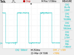
the above uses the rising edge of a square wave (same frequency as sine wave but out of phase) to start the timer interrupts, e.g.
Thanks a lot for the code and description. It certainly will help once i switch to ESP32 which I have to later. Meanwhile I am using STM32 NucleoL with input from generator CD4060. I have recently tried Interrupt to find the time between rising and falling but am not sure if it actually gives the time I am looking for (that is the falling time in the attached picture). Compared to the data i see in the excel sheet the times are round about similar. And when moisture of soil is increased the time also increases. What do you think about this approach, am I really getting the rise/fall time here?
input on GPIO16 is a square wave frequency 10Hz period 100mSec
serial monitor displays time between rising and falling edges as 50mSec
50002
50002
50001
50002
50002
50002
50002
50002
it is not recommended to call Serial.print() and similar functions in interrupt routines, e.g. they cause an exception on the ESP32
generally save data to volatile variables and print in loop() (as in the above code)
Thanks. I tried your suggestion about serial in loop and it works. One more thing. Like your code I also have to find amplitude (to get electrical conductivity) but that will require finding the minimum and maximum and for that input data is required to be read by analogRead. I know it cannot be read on the same pin while interrupt is in use. I see in your code for ESP32 (mine right now is STM32) that you read the data first (to get amplitude) and then call the interrupts to find time. With my code how can I read the signal from the same pin?
Tried that, changed the analog pin PB0 to D7 to get the pwm and for the voltage used PB0 but the code crashes after the first pwm value. It seems because of the analogRead inside the interrupt?
Thanks. It was crashing because of the Serial.printf("voltage %f\n", voltage);
maybe on execution it crashes there. Changed the printf to println and removed 'voltage %f\n' and it worked and gives both the pwm and the voltage. Amazing!