The LED was a last minute addition as well. When starting with Arduino a resistor is just a resistor but now when picking actual parts they are a new challenge
With a 5 mA LED that has a Vf 2,9V on a (max) 24V circuit I calculated a 4220 Ohm resistor, but now I see this 125mW Thick Film Resistor has "125mW" in front of it. As I said before I don't fully grasp datasheets and the only thing I'm getting is it's a power rating. So 1/8W, does this mean the load after the resistor cannot exceed 1/8W. I figure with 5mA and 2,9V I'll have 0.0145W so I'm good.
If I end up using a 12V supply I guess I'll hardly be able to see it though.
The voltage Vin should be kept between 9 to 7V.
Any more than 9V you will be tasking the onboard 5V regulator.
Possibly burning the regulator out if too much current flows thru it.
Remember Voltage(across the reg) * Current(thru reg) = Watts
Example: Assume Current was 500mA (24V - .2V(diode) - 5V) * 500mA = 9.4 Watts
If the Power LED is put on the 5V line, the intensity will be constant.
Don't forget to add the DH22 Pull-Up resistors.
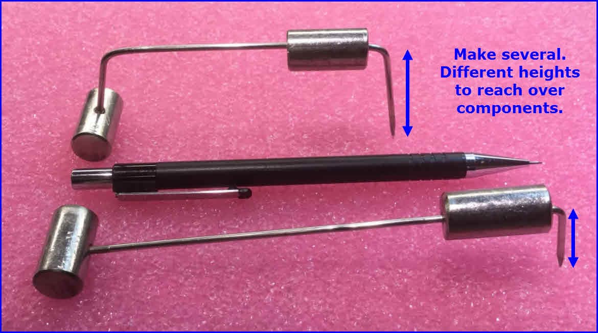
I sometimes use two pads side by side (1/10th apart) for a Test Point.
You solder #24 or #26 bare Bus Bar Wire between these two pads giving an arch/loop.
This then gives you something to clip on to with a scope probe etc.
I only did a cursory check on your schematic.
BTW
21V / .005A ~ 4.2k not 4220k as in the silk screening for R5.
21V * 5mA = 105mW which is < 125mW
FYI a 1206 is 1/4 Watt
I added these to the bottom. I have a floating one I'd like to place on the lower trace at the right, but I can't find out how to position it at a 45 degree angle. Perhaps this is not possible? result in later post
The DHT22s are on tiny breakoutboards that have their own pull-up resistor of 5K. Would an aditional one on the PCB still be beneficial?
Somehow I got into the mindset to build everything to account for maximum tolerances, and then continued on like that was the basic default.
As @LarryD also indicated I think I'll stick to 9V.
Sounds like a plan!
If I take 5V, account for 2.9V voltage drop and put 1mA into the calculator I get 2.1K Ohm. Putting that into the schematic and moving the led.
Sounds like a handy solution! However I'm hesitant to have exposed wires like that, plus with the symplicity of this project I won't be using anything as advanced as a scope probe. Advanced to me at least, I have no idea what it is
After removing the top pour and all the vias connecting them I'm left with a few spots where there is no longer a GND connection on top. I've added a small trace with via to those, is that common practice/acceptable?
I changed the settings on the fill zone. Reduced clearance from 0.5 to 0.3 and changed connections from thermal relief to solid. This gave me some space to put some 0 Ω resistors on the lower trace.
Alright I've been thinking on it for a bit and I think I found some common ground (no pun intended) @camsysca & @LarryD
The long traces for the I2C that were on the bottom layer, I've moved them to the top layer. I had to rotate the TFT connector 180 degrees to make space but I figure I can do the wires from the connector to the TFT any way I want them.
No more long traces on the bottom layer and no more need for jump over bridges. So a nice big GND field and return paths the I2C traces wouldn't otherwise have.
To accomplish this I've added a trace in between them starting and ending in a via. What do you think?
That's a great idea, however since I've been experimenting with the production files and uploading everything to the manufacturer I know this would cost me about € 40,00 extra to go from 1-sided to 2-sided assembly.
I know I could indeed solder them myself, but I have no experience with SMD soldering, nor any of the tools to make that easier. For this particular project I'll choose for them to mount everything and for me to be lazy and compromize a little