First Robot Project - A Few Issues

I've been buying a few cheap pieces off eBay and using what I had around to finally get going with my first robotic project.

After viewing several videos and tutorials I decided to use a L293D chip from a motor controller board I had bought as it allowed more freedom with spare pins as I only needed to control two DC motors.

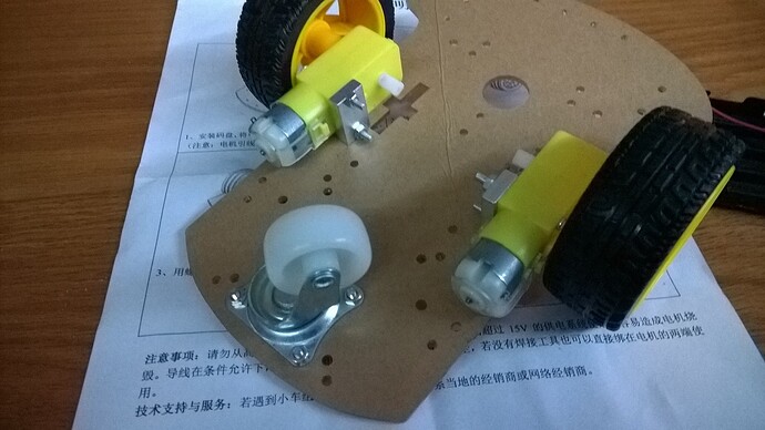
The first two images show the cheap robotic base I bought from China for £7. It has two 6V DC motors.

On the second two images it shows the full robot that I made. It is being powered by a 9.6v rechargeable pack for a remote control car. This is going through a voltage regulator to put out 5V for the motors. I know that this is not the best way but is certainly the quickest for me to have something working.

To allow the robot to roam without any trailing cables the UNO is being powered by a rechargeable 9V battery.

The fifth image is the schematic of the wiring (looks like a birds nest in the images :slight_smile: ).

Further below is the code that I've used.

Now I have a few main issues that hopefully are easy to get over.

Firstly when I was testing all the controls with the robot sitting on a stand so the wheels would spin without it shooting off I would find a couple of things. Sometimes when you set it to go forwards (both wheels travelling at the same time) only one wheel would start up and run at around half speed. If I set it to loop through a couple of commands and run the forward again it ran fine. :frowning:

Secondly on one of the motors I was unable to get it to run in reverse. This was on pins D1 / D2 where it was as if D1 would go LOW but D2 would not go to HIGH.

Thirdly I also tried to use PWM on pins D10 / D11 to vary the speed of the motors. Sometimes this would work and other times this would not. The code shows everything as digitalWrite but for the leftMotor and rightMotor on pins D10 / D11 these were written as the proper analogWrite so the code is not a mistake just how it was changed to work.

Lastly when I set the robot off on the floor with a simple go forwards and if the sensor picked something up within 50cm do a left turn it all worked fine except that the robot had a slightly quicker drive on the right motor. This results in the robot doing a slight left turn where had it got the space would probably run around in a 3 or 4 meter wide circle.

I'm not sure if these are related to the power I'm using to drive the motors as I'm using a 5V regulator. I'm sure that some of these can easily be resolved.

Hopefully the video / link below will work on the robot running in circles.

Robot Video

The Code.

#include <NewPing.h>

#define TRIGGER_PIN  7  // Arduino pin tied to trigger pin on the ultrasonic sensor.
#define ECHO_PIN     6  // Arduino pin tied to echo pin on the ultrasonic sensor.
#define MAX_DISTANCE 200 // Maximum distance we want to ping for (in centimeters). Maximum sensor distance is rated at 400-500cm.

NewPing sonar(TRIGGER_PIN, ECHO_PIN, MAX_DISTANCE); // NewPing setup of pins and maximum distance.

// --------------------------------------------------------------------------- Motors
int motor_left[] = {1, 2};
int motor_right[] = {3, 4};
int leftMotor = 10;
int rightMotor = 11;
int motorSpeed = 255;

// --------------------------------------------------------------------------- Setup
void setup() {
  Serial.begin(9600); // Open serial monitor at 115200 baud to see ping results.

// Setup motors
int i;
for(i = 0; i < 2; i++){
pinMode(motor_left[i], OUTPUT);
pinMode(motor_right[i], OUTPUT);
}
pinMode(leftMotor, OUTPUT);
pinMode(rightMotor, OUTPUT);
}

// --------------------------------------------------------------------------- Loop
void loop()
{
  delay(50);                      // Wait 50ms between pings (about 20 pings/sec). 29ms should be the shortest delay between pings.
  unsigned int uS = sonar.ping(); // Send ping, get ping time in microseconds (uS).
  Serial.print("Ping: ");
  Serial.print(uS / US_ROUNDTRIP_CM); // Convert ping time to distance in cm and print result (0 = outside set distance range)
  Serial.println("cm");
  
  if(uS / US_ROUNDTRIP_CM > 50)
  {
    drive_forward();
    digitalWrite(leftMotor,HIGH);
    digitalWrite(rightMotor,HIGH);
  }
  else
  {
    motor_stop();
    turn_left();
    digitalWrite(leftMotor,HIGH);
    digitalWrite(rightMotor,HIGH);
  }
  
}

// --------------------------------------------------------------------------- Drive

void motor_stop()
{
  digitalWrite(leftMotor,LOW);
  digitalWrite(rightMotor,LOW);
}

void drive_forward()
{
  digitalWrite(motor_left[0], HIGH); 
  digitalWrite(motor_left[1], LOW); 
  
  digitalWrite(motor_right[0], HIGH); 
  digitalWrite(motor_right[1], LOW); 
}

void drive_backward()
{
  digitalWrite(motor_left[0], LOW); 
  digitalWrite(motor_left[1], HIGH); 
  
  digitalWrite(motor_right[0], LOW); 
  digitalWrite(motor_right[1], HIGH); 
}

void turn_left()
{
  digitalWrite(motor_left[0], LOW); 
  digitalWrite(motor_left[1], HIGH); 
  
  digitalWrite(motor_right[0], HIGH); 
  digitalWrite(motor_right[1], LOW);
}

void turn_right()
{
  digitalWrite(motor_left[0], HIGH); 
  digitalWrite(motor_left[1], LOW); 
  
  digitalWrite(motor_right[0], LOW); 
  digitalWrite(motor_right[1], HIGH); 
}
Or should this be in the motors section?

I've recently built myself a robot using a cheap kit from China and have a couple of issues.

Sorry for any duplication but I created this thread in the Projects section without any replies.
Project Thread
I thought I had better place it in this section as it is a motor / power issue.

The original thread gives a full list of the code, schematics and photos that I've taken.

My issues are as below. Which I've just read another posting in this section on the L293, so wondering if it is not just a power issue but a mix of the power and chip.

I will have to do a check on what power is coming out of the chip to see how much less than the 5V is being supplied to the motors.

Firstly when I was testing all the controls with the robot sitting on a stand so the wheels would spin without it shooting off I would find a couple of things. Sometimes when you set it to go forwards (both wheels travelling at the same time) only one wheel would start up and run at around half speed. If I set it to loop through a couple of commands and run the forward again it ran fine. :frowning:

Secondly on one of the motors I was unable to get it to run in reverse. This was on pins D1 / D2 where it was as if D1 would go LOW but D2 would not go to HIGH.

Thirdly I also tried to use PWM on pins D10 / D11 to vary the speed of the motors. Sometimes this would work and other times this would not. The code shows everything as digitalWrite but for the leftMotor and rightMotor on pins D10 / D11 these were written as the proper analogWrite so the code is not a mistake just how it was changed to work.

Lastly when I set the robot off on the floor with a simple go forwards and if the sensor picked something up within 50cm do a left turn it all worked fine except that the robot had a slightly quicker drive on the right motor. This results in the robot doing a slight left turn where had it got the space would probably run around in a 3 or 4 meter wide circle.

I'm not sure if these are related to the power I'm using to drive the motors as I'm using a 5V regulator. I'm sure that some of these can easily be resolved.

First, don't use a voltage regulator on your motors. That's like towing a car with a piece of string. It works, but you can go faster.

Your motor drivers will regulate the voltage to the motor. If they are 5v motors and you have a 9v battery, then you probably shouldn't exceed 60% drive except for short periods. Check if the motors are getting hot after a long drive and then turn this limit up or down in your software.

Second, how is the Arduino powered? Is it connected directly to 9v or is it sharing the motors' 5v? Sharing is bad. Connect the Arduino's Vin to 9v.

I suggested to the Moderator to merge the other Thread with this one and then he did it and I lost my reply .....

I presume you are using DC motors (and not stepper motors).

The L293 will have a considerable voltage drop - it's probably better to power it directly from the batteries

A PP3 type of 9v battery cannot provide enough current and runs flat very quickly. Use AA NiMh batteries or just use a trailing power cord while testing.

Draw a diagram showing how everything is connected and post a photo of the drawing. Drawings are easier to figure out than photos of hardware.

...R

That looks like a pretty good 9.6v battery in the photos. I think the OP is on the right track.

From the original post

To allow the robot to roam without any trailing cables the UNO is being powered by a rechargeable 9V battery.

I don't think this refers to the 9.6v battery.

...R

Langy:
Sometimes when you set it to go forwards (both wheels travelling at the same time) only one wheel would start up and run at around half speed. If I set it to loop through a couple of commands and run the forward again it ran fine. :frowning:

Intermittent issues like that can often be loose wiring. If it starts acting up like that in the future, try pushing and moving some of the wires to see if it corrects the behavior. Those jumper wires and breadboards are real handy and easy to work with, but they don't always make the best connections. I've had bad jumper wires where the wire is not properly connected to the pin: it gives poor performance, and then the pin and plastic covering falls off of the wire. >:(

I've also had it where the pin on the jumper wire doesn't make good connection with the breadboard, even though the jumper wire and breadboard are new: just moving the wire a bit causes it to make or break the connection.

Secondly on one of the motors I was unable to get it to run in reverse. This was on pins D1 / D2 where it was as if D1 would go LOW but D2 would not go to HIGH.

Again, check your connections, and double check that everything is going to the right pins. The D2 line looks like it's hooked up properly in the picture, but it's so hard to tell on a picture.

Try putting an LED (with a dropping resistor) on that pin and see if you can make it change. It's possible that the pin circuit in the chip has become damaged and can no longer drive it properly. It's also possible that the pin on the motor controller chip is bad, as well. Take the D2 end of the jumper wire and temporarily connect it to ground and then 5V and see if the motor controller responds properly.

Thirdly I also tried to use PWM on pins D10 / D11 to vary the speed of the motors. Sometimes this would work and other times this would not. The code shows everything as digitalWrite but for the leftMotor and rightMotor on pins D10 / D11 these were written as the proper analogWrite so the code is not a mistake just how it was changed to work.

Show us the code that tries to drive the PWM pins. Maybe we'll see something.

Try hooking up an LED to those pins, and run the Fade example sketch to make sure the pin is working properly (of course, you'll have to adjust the sketch to change the pin numbers.

all worked fine except that the robot had a slightly quicker drive on the right motor. This results in the robot doing a slight left turn where had it got the space would probably run around in a 3 or 4 meter wide circle.

There are always some variations in motors, two different motors will never really turn at exactly the same speed. A two motor drive like that is very flexible and maneuverable, but very hard to make it go straight. When you get the PWM portion of it working, you may be able to tweak the settings by running one motor with a slightly different value than the other. But it will be hard to get it exactly right. The most reliable way to make it go straight is to put an encoder on each wheel so you can measure the speed of each wheel. Then your software will have a feedback loop that looks at the actual wheel speed, compares it to the desired wheel speed, and makes slight adjustments to the motor drive. But this is an advanced concept, you better of on concentrating on the basics first.

See my post on the "Curse of the L293D". It seems like all of my problems were due to crappy 9V batteries, then crappy alkaline AAs, and finally crappy Carbon-Zinc batteries. With decent (Enerloop) NiMH AAs, everything is purring along.

So if you aren't sure that your batteries are decent, make sure.

Of course, looking at your battery... It's way better than what I started with... Or finished with.

L293D and other darlington drivers lose 2.5 to 3V already, so you definitely shouldn't
regulate the 9.6V down at all - straight to the L293D motor supply, and with luck you'll get
7V max to the motors, no problem since you can limit the PWM as you see fit.

Regulating down to 5V would mean only about 2.5V to the motors, 70% of your power
wasted....

Hi Langy,
As it's been said, don't power you motors thro' a regulater, your motors will need more current then it can supply. I now never use the L293/98 has you lose 2v+ on the output so you're 5v to the motors might be 3v, give the motors the full battery voltage. 9.6v-2v=7.6 should be OK with them motors (6v)..

Don't use pins 0 or 1 as they are used for serial I/O and programming. PWM works differently for different motors! I find that any value under 50 does'nt move the motors at all.

Check all wiring and let us see a schematic... It's very unusual to buy two motors that run at the same speed, use PWM to even this out by runiing the slower motor, with an higher value, you'll have to experiment a bit to get it right.

I started with one of these chassis too, but you can see my newer bots here:www.melsaunders.co.uk under Electronics.

Hope it helps, Regards.

Mel.

Many thanks for all the replies.
For those after code and schematics they are all in the original post.

To clarify the setup , the actual Arduino is powered by a rechargeable basic 9V battery. As the Arduino will not be pulling much power itself I would have thought that this would have covered it's use for small periods. The main power source is from the large 9.6V power supply. This is one from a RC car so designed for powering motors and longer periods of use.

I think the first thing I will do is see how much voltage is coming out of the L293 chip top power the motors, yes they are DC and not stepping motors.

On order I also have some of those cheap voltage converter boards which should hopefully turn up in the next couple of weeks to get the voltage to the correct level.

As to the motors running at different speeds I have already had delivered the encoders as that is what I was planning for the future.

I will run some tests and report back as to what I find in the next few days.

Langy:
Arduino is powered by a rechargeable basic 9V battery

If this is a PP3 sized battery I doubt if it will be suitable. The problem is that if it is not producing enough current the symptoms may look like software problems on which you waste endless hours of time. Either use the USB connection for power or a set of AA NiMh batteries while you are doing your development. Then when it works you can see how well the small 9v battery works.

...R