revenons à nos moutons...
je passe rapidement les éléments mécano-optiques qui fonctionnaient déjà en manuel
Un bloc de mise au point d'un ancien microscope nikon Optiphot
Dessus un bon vieux soufflet macro
un objectif de microscope à un bout et un appareil photo à l'autre (voir 1ère photo)

Ensuite un moteur pas à pas de récup avec sa courroie soigneusement fixé (voir photo 2)

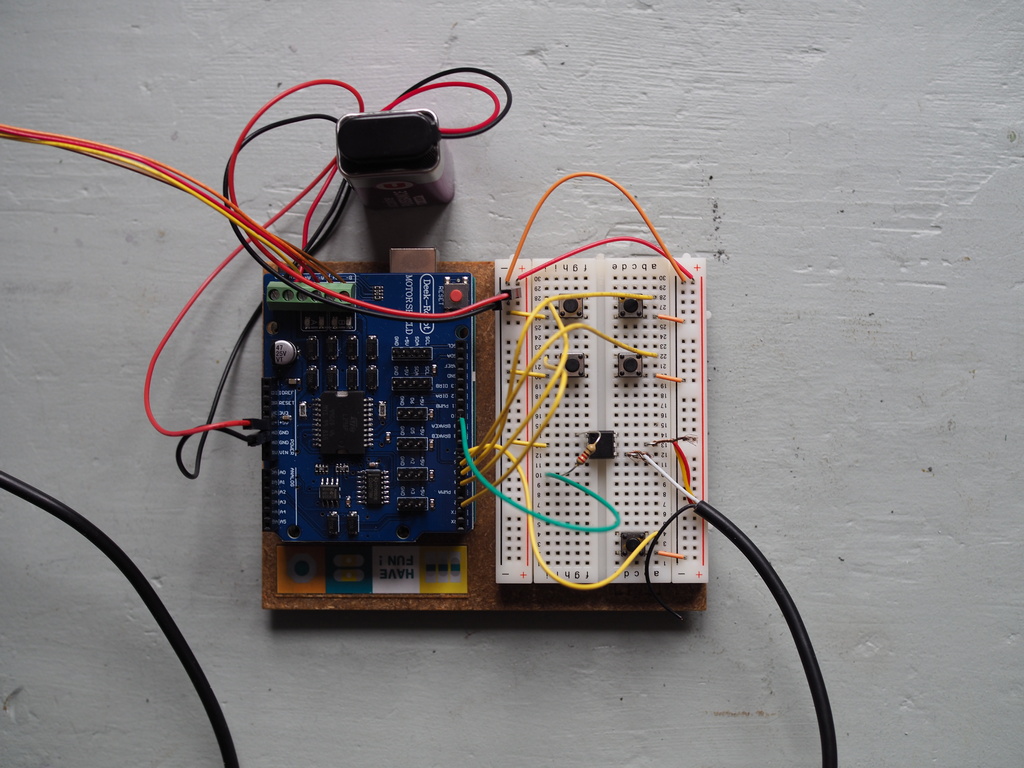
Enfin (photo 3) un arduino Uno et son shield moteur. 5 interrupteurs, un optocoupleur plein de fils moches
pour l'instant un code minimal pour les fonctions suivantes :
un bouton pour avancer
un bouton pour reculer
un bouton pour remettre la variable de position (t) à 0 (point de départ)
un bouton pour mémoriser la position de fin (encore dans t)
un bouton pour :
revenir à la position de départ
avancer d'une fraction de tour (pas)
pendant un certain nombre de cycle (fin - début)/pas
entre deux avances un déclenchement d'appareil photo grâce à un optocoupleur
int debut=0;
int fin=0;
int t=0;
int delaylegnth = 10;
int pas=17;
int Cycle=0;
int x=0;
int y=0;

void avance()
{
  digitalWrite(9, LOW);  //ENABLE CH A
  digitalWrite(8, HIGH); //DISABLE CH B

  digitalWrite(12, HIGH);   //Sets direction of CH A
  analogWrite(3, 255);   //Moves CH A

  delay(delaylegnth);

  digitalWrite(9, HIGH);  //DISABLE CH A
  digitalWrite(8, LOW); //ENABLE CH B

  digitalWrite(13, LOW);   //Sets direction of CH B
  analogWrite(11, 255);   //Moves CH B

  delay(delaylegnth);

  digitalWrite(9, LOW);  //ENABLE CH A
  digitalWrite(8, HIGH); //DISABLE CH B

  digitalWrite(12, LOW);   //Sets direction of CH A
  analogWrite(3, 255);   //Moves CH A

  delay(delaylegnth);

  digitalWrite(9, HIGH);  //DISABLE CH A
  digitalWrite(8, LOW); //ENABLE CH B

  digitalWrite(13, HIGH);   //Sets direction of CH B
  analogWrite(11, 255);   //Moves CH B

  t++;
  delay(delaylegnth);
  }

void recule()
{
    digitalWrite(9, LOW);  //ENABLE CH A
  digitalWrite(8, HIGH); //DISABLE CH B

  digitalWrite(12, HIGH);   //Sets direction of CH A
  analogWrite(3, 255);   //Moves CH A

  delay(delaylegnth);

  digitalWrite(9, HIGH);  //DISABLE CH A
  digitalWrite(8, LOW); //ENABLE CH B

  digitalWrite(13, HIGH);   //Sets direction of CH B
  analogWrite(11, 255);   //Moves CH B

  delay(delaylegnth);

  digitalWrite(9, LOW);  //ENABLE CH A
  digitalWrite(8, HIGH); //DISABLE CH B

  digitalWrite(12, LOW);   //Sets direction of CH A
  analogWrite(3, 255);   //Moves CH A

  delay(delaylegnth);

  digitalWrite(9, HIGH);  //DISABLE CH A
  digitalWrite(8, LOW); //ENABLE CH B

  digitalWrite(13, LOW);   //Sets direction of CH B
  analogWrite(11, 255);   //Moves CH B

  delay(delaylegnth);
  t--;
  }

 void shoot()
  {
  digitalWrite(10, HIGH);  // pull pin 2 HIGH, activating the optocoupler
  delay(100); // give the optocoupler a moment to activate
  digitalWrite(10, LOW);  // pull pin 10 low until you're ready to activate again
  }

void stack()
  {
  while(x<=Cycle-1)
  {
  while(y<=pas)
  {avance();
  y++;
  }
delay (1000);
shoot();
delay(4000);
x++;
y=0;
}
}
void setup() {
  //establish motor direction toggle pins
  pinMode(12, OUTPUT); //CH A -- HIGH = forwards and LOW = backwards???
  pinMode(13, OUTPUT); //CH B -- HIGH = forwards and LOW = backwards???
   pinMode(10, OUTPUT);
  //establish motor brake pins
  pinMode(9, OUTPUT); //brake (disable) CH A
  pinMode(8, OUTPUT); //brake (disable) CH B
  pinMode(2,INPUT_PULLUP);
  pinMode(4,INPUT_PULLUP);
  pinMode(5,INPUT_PULLUP);
  pinMode(6,INPUT_PULLUP);
  pinMode(7,INPUT_PULLUP);
Serial.begin(9600);
}
void loop() {

 boolean etatBouton1 = digitalRead(2);
 boolean etatBouton2 = digitalRead(4);
 boolean etatBouton3 = digitalRead(5);
 boolean etatBouton4 = digitalRead(6);
 boolean etatBouton5 = digitalRead(7);

  if (etatBouton1==LOW)
  {avance();
  }
  else if(etatBouton2==LOW)
  {recule();
  }
  if (etatBouton3==LOW)
  {t=0;
  debut=t;}
  if (etatBouton4==LOW)
  {
  fin=t;
  Cycle=(fin-debut)/pas;
  }
  if (etatBouton5==LOW)
  {
  while(t>0)
  {
  recule();
  }
  delay (2000);
  stack();
  }

Serial.println("valeur de t");
Serial.println(t);
Serial.println("valeur de début");
Serial.println(debut);
Serial.println("valeur de fin");
Serial.println(fin);
Serial.println("nombre de cycle");
Serial.println(Cycle);
}
Bon... tout ça c'est un premier jet et mérite d'être optimisé...
ma première question c'est l'alimentation
visiblement la carte alimente le moteur quand elle est reliée au PC... Normal ?
quand je débranche, je peux alimenter le moteur avec une pile 9V qui du coup alimente aussi la carte ... Normal ?
comment découpler les deux alim pour alimenter la carte en 5V et le moteur en 12V
Cordialement
Dominique