Four DD motors all spinning at different speeds.

Hi all! This is my first forum post, so I apologize for any lack of decorum my post has. Feel free to correct any errors you see .(actual problem statement is below my code, if you want to skip the background) I have done some work with Arduino before, and made some basic inventions (like a machine that stirs your coffee), but I do not have a ton of experience with circuitry, and have never been formally trained. I am trying to make a quadcopter using normal DC motors, not the ridiculously overpriced ones on Amazon, and I have tried many different approaches with motor drivers, but they are usually too heavy or need too much power or something else. I decided to make my own drivers with this tutorial:

I used 2N2222 NPN transistors, 270 ohm resistors, a 3.7v lipo battery, and 1N4001 flyback diodes. The motors I got are here: https://www.amazon.com/USAQ-Coreless-Brushed-8-5x20mm-Propeller/dp/B06Y11C2HL/ref=sr_1_6?dchild=1&keywords=4+small+dc+motor+with+propeller&qid=1609860121&sr=8-6
I have attached a png file of my circuit diagram, and my code is below:

void setup() {
  // put your setup code here, to run once:
pinMode(3,OUTPUT);
pinMode(5,OUTPUT);
pinMode(6,OUTPUT);
pinMode(9,OUTPUT);
}

void loop() {
  // put your main code here, to run repeatedly:
  analogWrite(3,100);
  analogWrite(5,100);
  analogWrite(6,100);
  analogWrite(9,100);
 

}

The problem is, whenever I run this code, the motors on pin 3 and pin 6 don't run (they spin very slowly at higher speeds) while the other two motors spin quickly. I have switched motors out, changed out transistors, checked wiring, and looked for others with this problem. I found someone with a similar problem, and it was decided that he was exceeding the draw current limits of the 2N2222 transistor. I have looked at the datasheet for this transistor, and I made a point of ordering motors with specs that would not overwhelm it. (specs can be found on the amazon link above). I also made a copy of the circuit on the Tinkercad circuit simulator, and all of the motors ran at the same speed with no problem. (they tell you the RPM) Any help or advice would be appreciated, and feel free to double check check my work. Thanks for reading this really long entry!

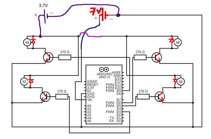
In the beginning, did you connect all 4 motors to the power source and confirm the all ran at the same speed?

Paul

Hello and welcome.
++Karma; // For posting your code correctly and including a schematic on your first post.

Now please revise your schematic:

The transistors, diodes and battery are the wrong way round.

  • Diode cathode to positive
  • Transistor emitter to 0V
  • Battery long side is positive

I'm unsure about this and happy to be corrected

but I dont think you should be repeating your analogwrites so quickly,

so could you try adding delay(1000); to your code?

Then try commenting out all but one channel at a time to see if each runs correctly on its own?

I'm not convinced that Uno is doing anything with only 3.7V connected to Vin (which needs a minimum of 7V).

Also your motor specification is lying to you. There is no way on earth that those motors can turn 65mm props at over 50,000rpm and take only 100mA. Even 10 times that current is probably too low.

Steve

I agree with slipstick about the questionable specs for the motor.

Anyway ------ OP ----- this amended diagram can help with at least getting the motors to turn. Let me know if I slipped up anywhere in doing the mods.

"Operating Current: 0.08A-0.1A" :o
I even doubt if 'free-running' is that low.
With a prop it's much higher.

Expect a stall current of 5-8A
A 2N2222 is just silly. You will need mosfets with low Rds(on)@5volt.
Leo..

True ---- I agree with wawa.

Go for transistors like FQP30N06L, a N-channel logic-level mosfet. Or FDP65N06.

Will it matter with your motors that the PWM frequency on pins 5 and 6 will be about 980 Hz while the other pins will be about 490 Hz in the case of an Arduino Uno? I am not sure if this matters or not as to your motors. It is unusual that it shows up on pins 3 & 6. Again, while I don't see where the PWM frequency would matter I figured I would toss it out there.

Ron

Hi there Ron. Generally - for these remote control quad copters etc ....... the overall control system makes automatic adjustments to the speed of the motors, all going towards making the craft do something, like maintain a certain angle or maybe even height.

PWM frequency can definitely be a consideration ---- as in how a motor responds are various significantly different PWM frequencies.

Maybe not too much difference between 490 Hz and 980 Hz.

I think it's a really good question and comment you made. Also - the kinds of motors they usually use for quadcopters - such as brushless dc motors etc have inbuilt devices for measuring RPM etc. While these other sorts of motors, like brushed DC motors ------ maybe don't have that sort of feature.

And ----- for the OP ----- for the motors that do spin at a fast speed ------- what happens if you temporarily replace those fast spinning motors with those slow spinning ones ----- that is driving the slow-spinning ones with the driver outputs that are 'working'? Do those slow spinning ones become fast spinning when driving with the drivers that are 'working'?

I don't want to rain on your parade but I think your
objective is unrealistic for a couple of reasons.

  1. Brushless motors have a higher power to weight ratio than DC motors.
  2. Brushless ESCs have a much better heat dissipation map because the use many small mosfets to distribute the heat more evenly rather
    than concentrating all the heat from one motor in a single device. Do you have any heat sinking ?
  3. Agree with Wawa. Using 2N2222s is a NO GO.
  4. Those are really small motors with really high
    rpm. I had a couple of those I used for small fixed wing aircraft. They're cool motors but I'm
    not convinced you'll get enough power with one
    3.7V battery.
    What is your RTF weight ?
  5. Do you have a flight controller ?
  6. Accelerometers
  7. GPS ?
  8. Have you calculated your flight time ?
  9. WHAT is a DD motor ? (never heard of it)

Thank you all for responding so soon. I am amazed at how prompt and helpful this wonderful community is! I will try to answer some of the questions you all have asked me, and I really appreciate your contributions.
I have switched the slow moving motors with the fast moving motors, and the problem is not with the motors. I have connected the motors independently to the same power source, and they span at the same speed. "DD motors" do not exist to my knowledge, that was a typo on my part :). I have attempted larger power sources, and I have powered the arduino separately, with the same problems. I made the schematic right before posting the question, so there might be errors. I have yet to get the drone in the air, so I cannot measure flight time (zero minutes, if you want a specific number). I will continue to update as more responses (hopefully) come in, and tell me if I missed a question. Now I have a few questions to ask in return:
If I used the MOFSETS recommended by various users, would my schematic change, or would it just be a change in transistors (I can find the difference in base, collector, and emitter pins, as it I imagine it varies with the specific MOFSET. Also, why are 2N2222s deficient? I checked their specs and made sure to purchase motors that would not strain them. Also, the tutorial I linked above used the PN2222, which is very similar to the 2n2222, and made no mention of overstraining them (This is not criticism, I am genuinely curious). I was also unaware of the difference in frequencies of the PWM pins, which could certainly be the case. I will post more answers to questions and updates after I try this. Thanks once again to the kind souls who took the time to help someone in need.

Also, here is a revised diagram thanks to Perry. Sorry for the amateur mistakes :).

I'm on a phone so brief answer.

Thanks for the update and the much improved schematic. If you use MOSFETs the connections are called drain, source and gate. For an N Channel MOSFET, which is what you need, they correspond to
Emitter > Source
Base > Gate
Collector > Drain
MOSFETs are better because they have very low on resistance and draw virtually no current into their gate connection.

.. while the other two motors spin quickly

While not denying the benefit of using the right MOSFETS, if the motors are spinning quickly I would read that as confirmation the circuit is working using 2n2222

So to repeat my earlier post, I dont think you should be repeating your analogwrites so quickly,

so could you try adding delay(1000); to your code?

Then try commenting out all but one channel at a time to see if each runs correctly on its own?

I have yet to get the drone in the air, so I cannot measure flight time (zero minutes,

FYI, the way it works is the following:
step-1: measure full power current from battery
step-2: ascertain Lipo battery discharge "C" rating (25C,45C, etc)
step-3: ascertain Lipo battery mAh rating (from label on battery or package)
step-4: calculate flight time (assuming thrust to weight ratio>weight

Example:
Lipo Battery Rating: 1245mAh/25C
IBATTmax= mAh x C rating
= 1245mAh x 25C
= 31,125mA
= 31.125A
motor currentFULL THROTTLE = 2000mA (500mA/per motor)
Calculate Full Throttle Battery Current
Flight Time = 1245mAh/motor currentFULL THROTTLE
= 1245mAh/2000mA
=0.6225 hours
= 0.6225 x 60minutes/per hour
= 37.35 minutes

IMPORTANT NOTE: Above calculation does NOT take into account RTF weight (Ready To Fly weight)
It is mandatory that thrust to weight ratio be >1 for flight.
Obviously, the greater the weight, the more throttle is needed to lift off (the more throttle, the more current)
Measuring motor current on the bench does not guarantee flight.
To guarantee flight it is necessary to know RTF WEIGHT in order to calculate THRUST to WEIGHT ratio to
ascertain if it is indeed >1.

What is your RTF weight ?
** What is your FULL THROTTLE motor current ?**
5. Do you have a flight controller ?
6. Accelerometers
7. GPS ?

  analogWrite(3,100);[color=#222222][/color]
  analogWrite(5,100);[color=#222222][/color]
  analogWrite(6,100);[color=#222222][/color]
  analogWrite(9,100);

Why are you commanding "100" instead of 255 ?

FYI, if you have a postal scale, you can secure the drone to the top of the scale and observe how much the weight
reading decreases when you increase the throttle.
Personally, I would not use the code you are using.
I would test the thrust incrementally by commanding 25 % (0.25255= 64), then 50% (0.5255=128) , 75% (0.75*255=192), & 100% (255).
I would measure the battery current for each of the above and record it.

While not denying the benefit of using the right MOSFETS, if the motors are spinning quickly I would read that as confirmation the circuit is working using 2n2222

@John,
I think you will have to agree that the On resistance of a 2N2222 is counter-productive.

Ok, so I tried a few different recommended approaches, with no great results (This is in no way a criticism, I'm just updating my situation for everyone kind enough to help). I thought that the frequency difference in pins 5 and 6 might be what was causing the motor disparity, but I switched the pins, with the same results. I also noticed a rather strange thing that happened with both the original setup and all of my modified setups. When I stared to power the motors up, they would turn on, then go off, then quickly go back on. This happened with no consistent pattern, and always stopped after a few seconds. I don't know if this means anything, but I figured it was worth a shot. I added a delay at the end of the main loop, with no noticeable difference. I even tried only running the slow motors, but they still ran at their usual (slow) pace*. Finally, I tried just using a digitalWrite on all of the pins, with a similar result. I was driving the motors at 100 pwm for 2 reasons, one practical and one scientific. The first reason was that I wanted to test if the pwm actually worked (it did), and the second was that, at least for two of the motors, full speed is pretty freaking fast, and I don't have a frame yet, so I just pick the motors up to see how fast they are going, which usually results in me getting hit by the propeller at some point. The majority of people seem to be recommending that I use a MOFSET, as it is better for this project in virtually every way. Some people have even recommended specific MOFSETS, which is great. If I were to use MOFSETS, would my schematic change at all? (other than the switch in transistors, obviously) Would I still need a flyback diode and resistor, or would I need more resistance? Any clarification would be great. Also, a big thank you to raschemmel, who patiently explained to me that there was a way to calculate flight time without the drone being able to fly, and then did the calculations for me. Sorry for the long update, and thank you to everyone helping me.

I didn't change much about the code, and what I did change I documented above, but this may be helpful to visualize where I'm at:

void setup() {
  // put your setup code here, to run once:
pinMode(3,OUTPUT);
pinMode(5,OUTPUT);
pinMode(6,OUTPUT);
pinMode(9,OUTPUT);
}

void loop() {
  // put your main code here, to run repeatedly:
  analogWrite(3,100);
  analogWrite(9,100);
  analogWrite(10,100);
  analogWrite(11,100);
  delay(1000);
 

}

*By "slow motors", I mean that the drivers were slow, not the actual DC motors themselves, which ran at a much faster speed when connected to the drivers that the "fast" motors were.

Please stop and read ALL the REPLIES to your post and respond to EACH and EVERY one of them and answer ALL
the questions that have been asked. You thanked us for replying and ignored all the replies and answered none of
the questions. If you want help, you need to pay attention and show enough courtesy to respond to each reply
individually and answer all of the questions.
You post.
We ask
You answer
It's really that simple.

PS- thanks for the acknowledgement . Unfortunately, you may not like all of my replies.

TO DO LIST
1. Paul_KD7HB Reply#-1
2. Perrybebbington Reply#-2
3. Johnerrington Reply#-3
4. Slipstick Reply#-4
5. Wawa Reply#-6
6. Southpark Reply#-7
7. Ron_Blain Reply#-8
8. Southpark Reply#-9
9. raschemmel Reply#-10 (check)
10. Perryingbebbington Reply#-13
11. Johnerrington Reply#-14

I apologize if I offended anyone or ignored any questions. I did my best to read through the replies and answer them in a single response while updating the forum on where I currently was, but apparently I missed some of them. I do not have any flight controller, accelerometer, or GPS. My plan was to use joysticks and a 433 MHZ receiver to communicate to the Arduino (this already works) and control motor speed via pwm. I do not have a RTF weight calculated, because I am having trouble spinning all four motors at the same time, so I felt that it would be putting the cart in front of the horse to get everything else together when the feature that defines a quadcopter was having problems. I appreciate you bringing this oversight to my attention. Please tell me if I missed any other questions, although I feel that I answered most of them in my previous update.

You could start by getting a clipboard and listing all of the replies and questions asked in Reply order and
answering them by Reply#.
I see a lot of unanswered questions, starting with the very FIRST REPLY:

In the beginning, did you connect all 4 motors to the power source and confirm the all ran at the same speed?

FYI, my understanding is that the question is in reference to powering the motors WITHOUT CODE OR ARDUINO
and THEN sending ONE PWM signal to ALL FOUR driver circuits simultaneously using an adequate power source.
It really helps if you slow down and describe your test setup.
ie:
I did the following:
step-1: connected [describe power source]
step-2: using switches or jumper wires, I connected power to each motor directly, bypassing the transistor circuits, and then the next until all were running
(with no props at this point)
step-3: I measured the battery current using a DMM in DC mA mode
step-4: Disconnected power.
step-5: Reconnected transistor driver circuits
step-6: Commanded {XXX] PWM to ALL 4 drivers.
step-7: measured PWM current at 1/2 throttle and full throttle
etc
etc
etc.